Anterior spinal implant

a technology of anterior spinal nerve and implant, which is applied in the field of orthopedic surgical procedures, can solve the problems of limiting the range of motion of the spine, threatening the critical elements, and affecting the function of the spine, and achieves the effect of resisting migration

Inactive Publication Date: 2005-07-07
EUROPEAN BIOINFORMATICS INSTITUTE
View PDF99 Cites 229 Cited by
  • Summary
  • Abstract
  • Description
  • Claims
  • Application Information

AI Technical Summary

Benefits of technology

[0012] It is a general object of the present invention to provide an anterior spinal implan

Problems solved by technology

Genetic or developmental irregularities, trauma, chronic stress, tumors, and disease, however, can result in spinal pathologies which either limit this range of motion, or threaten the critical elements of the ner

Method used


Image

  • Anterior spinal implant
  • Anterior spinal implant
  • Anterior spinal implant

Examples


Embodiment Construction

[0038] The following description of the preferred embodiment(s) is merely exemplary in nature and is in no way intended to limit the invention, its application, or uses.

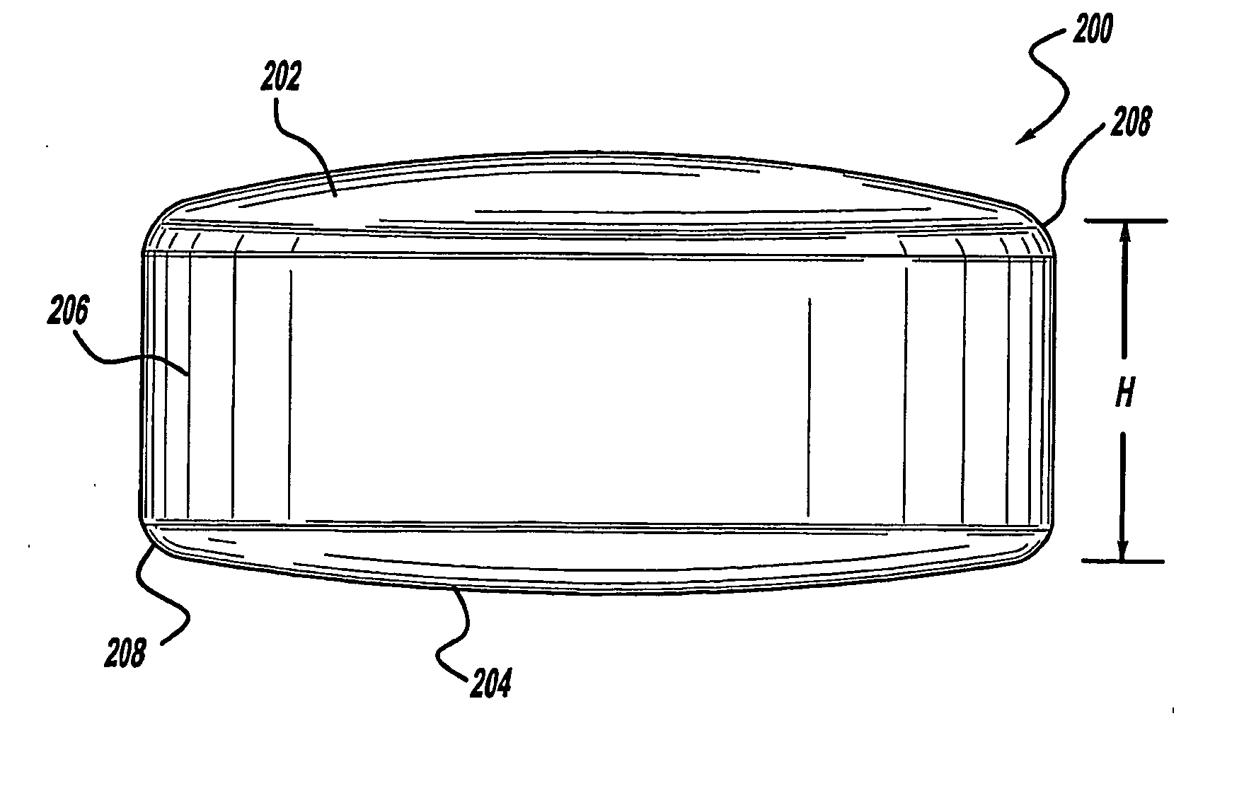
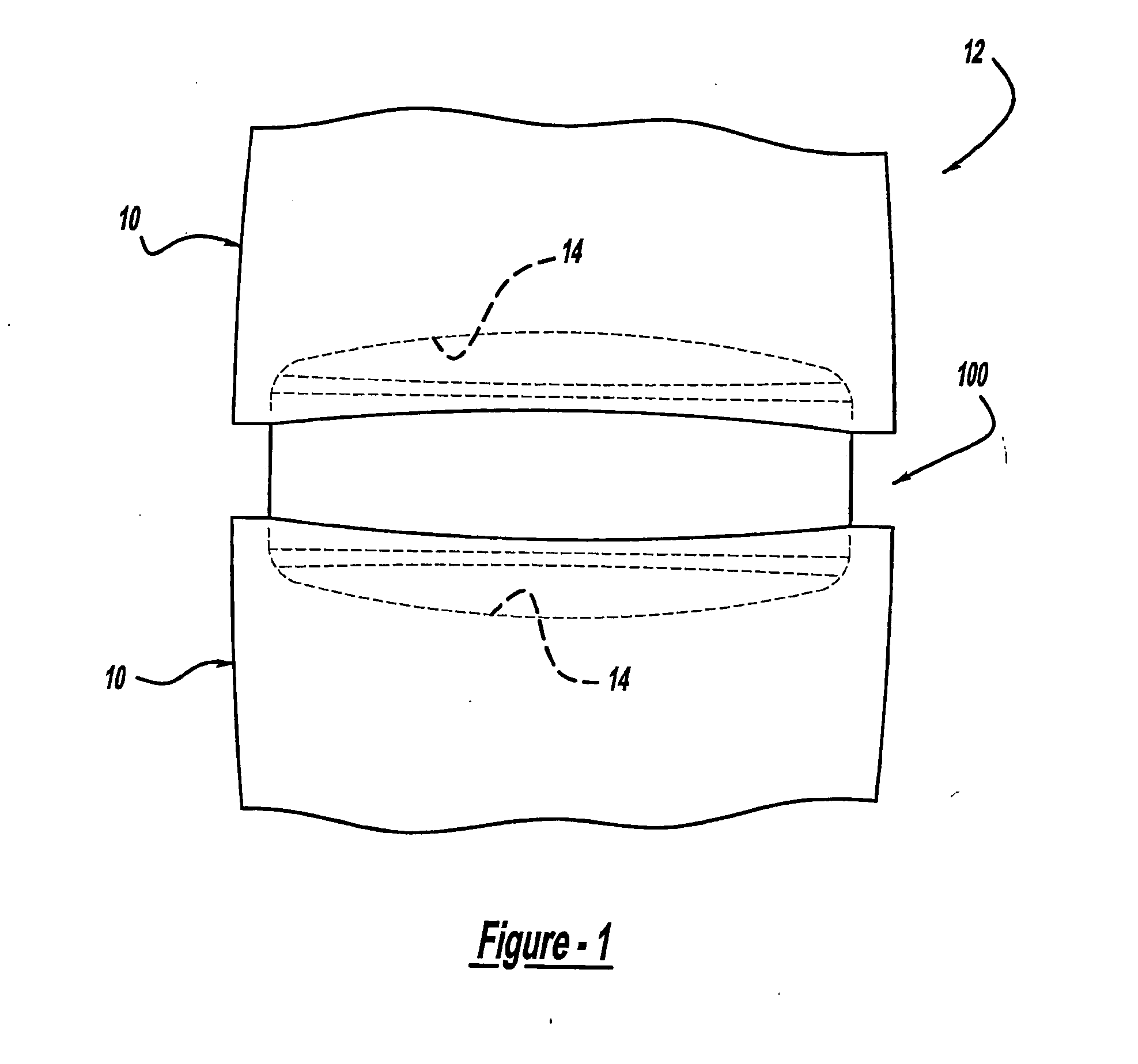
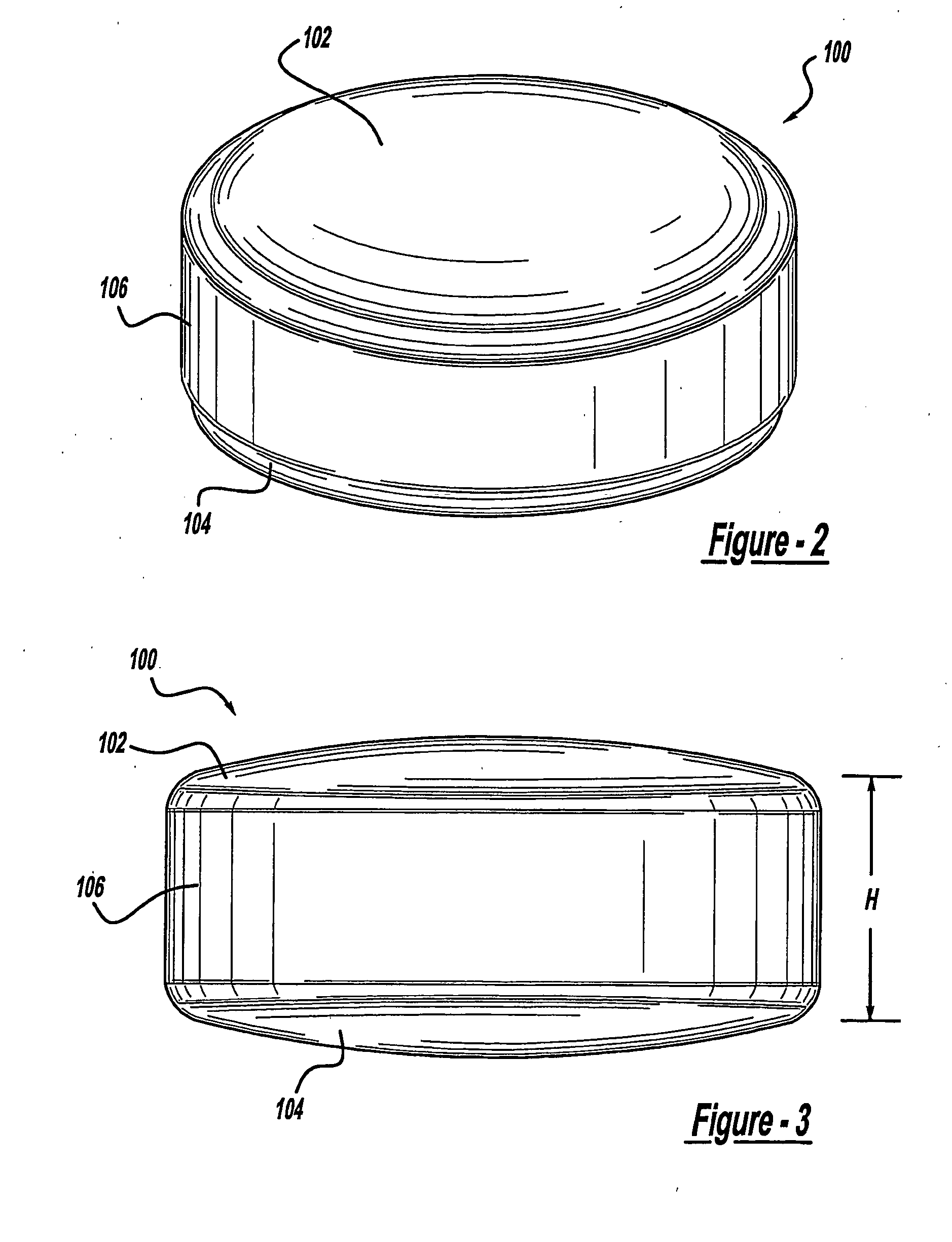
[0039] With initial reference to the simplified environmental view of FIG. 1, an anterior spinal implant constructed in accordance with the teachings of a first preferred embodiment of the present invention is illustrated and generally identified at reference character 100. The anterior spinal implant 100 is shown in the environmental view of FIG. 1 implanted between adjacent vertebral bodies 10 of a lumbar portion of a human spine 12. Those skilled in the art will readily appreciate that the application shown in FIG. 1 is merely exemplary. In this regard, the teachings of the present invention will be understood to be equally applicable for stabilizing other segments of the spinal column.

[0040] The anterior spinal implant is intended to abut the end plates 14 of the adjacent vertebral bodies 10. The remaining embo...


PUM


Abstract

An anterior spinal implant includes a superior end face, an inferior end face and a sidewall extending between the superior end face and the inferior end face. The superior end face and the inferior end face are convex. In one application, the superior and inferior end faces are convex. The sidewall includes a convexly curved leading portion, a convexly curved trailing portion and a pair of substantially planar side portions. The superior and inferior end faces transition in a sagittal plane from a first radius of curvature to a second radius of curvature. The first radius of curvature is smaller than the second radius of curvature. The apexes of the superior and inferior end faces are offset from a center of the implant.

Description

CROSS-REFERENCE TO RELATED APPLICATION [0001] This application claims priority to a provisional patent application which has been assigned U.S. Ser. No. 60 / 355,418, filed Feb. 7, 2002.FIELD OF THE INVENTION [0002] The present invention generally pertains to orthopedic surgical procedures. More particularly, the present invention pertains to anterior spinal implants. BACKGROUND OF THE INVENTION [0003] The human spinal column includes more than twenty discrete bones. These bones are generally similar in shape. Despite their similar shape, however, they do vary substantially in size in accordance with their individual position along the spinal column. The bones are anatomically categorized as being members of one of three classifications: cervical, thoracic, or lumbar. The cervical portion of the spinal column, which comprises the top of the spine up to the base of the skull, includes the first seven vertebrae. The intermediate twelve bones are thoracic vertebrae. The remaining five bo...

Claims


Application Information

Patent Timeline
IPC IPC(8): A61F2/00A61F2/28A61F2/30A61F2/44A61F2/46
CPCA61F2/28A61F2310/00359A61F2/4611A61F2002/30225A61F2002/3023A61F2002/30245A61F2002/30327A61F2002/30822A61F2002/4623A61F2230/0069A61F2230/0071A61F2250/0039A61F2310/00029A61F2310/00161A61F2/442A61F2/4603
Inventor COOK, STEPHEN D.BAILEY, KIRK J.ROUSSEAU, PATRICK
Owner EUROPEAN BIOINFORMATICS INSTITUTE
Why Eureka
Try Eureka