Method for making battery plates

a battery plate and plate body technology, applied in the field of battery plate modification, can solve the problems of lead-acid batteries failing in service, lead-acid batteries having lead-antimony grids that require periodic maintenance, water loss caused by gassing,

Inactive Publication Date: 2005-07-14
CPS TECH HLDG LLC
View PDF4 Cites 41 Cited by
  • Summary
  • Abstract
  • Description
  • Claims
  • Application Information

AI Technical Summary

Problems solved by technology

However, it was discovered that when a lead antimony alloy is used in battery grids, water loss occurs because of gassing.
Therefore, batteries having lead-antimony grids required periodic maintenance, i.e., the addition of water to the battery.
It is well known that lead-acid batteries will eventually fail in service through one or more of several failure modes.
One such failure mode is failure due to corrosion of the grid surface.
Electrochemical action corrodes the grid surface and reduces the adhesion between the active material and the grid (e.g., failure of the battery occurs when the grids are no longer able to provide adequate structural support or current flow due to the separation of the active material from the grid).
A low formation efficiency of positive plates requires a high formation charge.
Inefficient charging also leads to deficiencies in the resulting batteries assembled with such plates.
Typically, the initial capacity (performance) of the battery is low if the battery is not completely formed, requiring additional cycling to reach specific performance values.

Method used


Image

  • Method for making battery plates
  • Method for making battery plates
  • Method for making battery plates

Examples


example 1

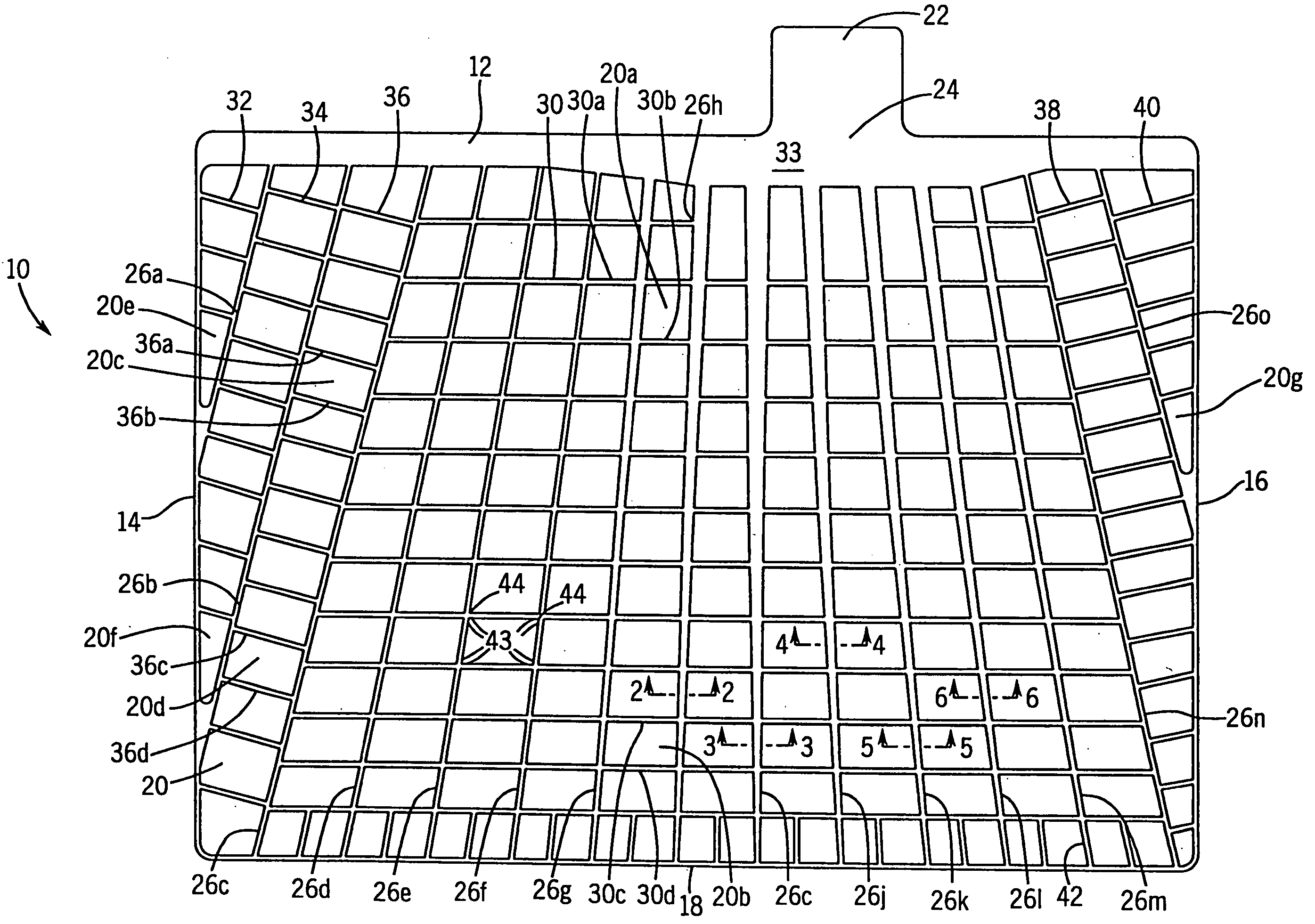
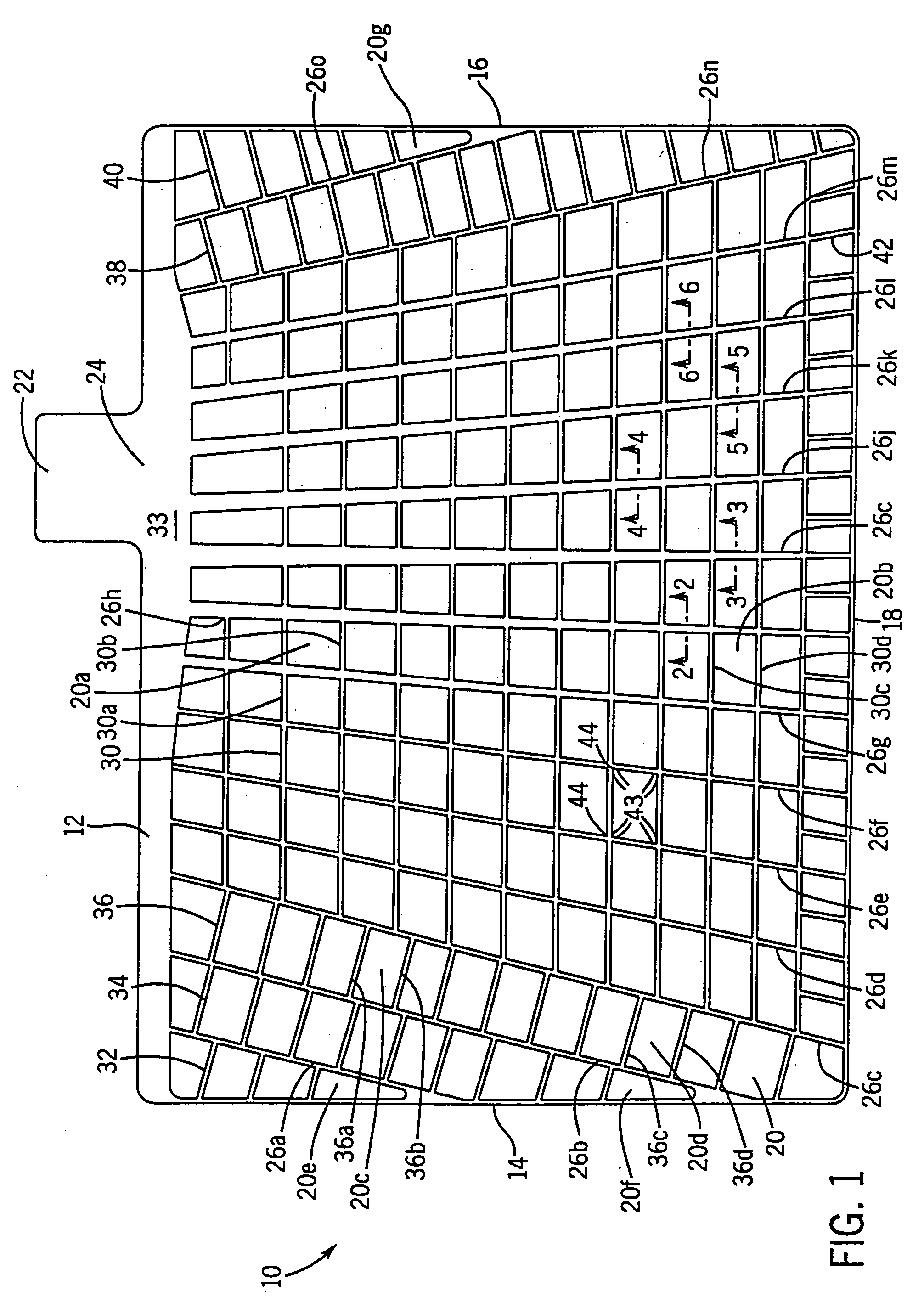
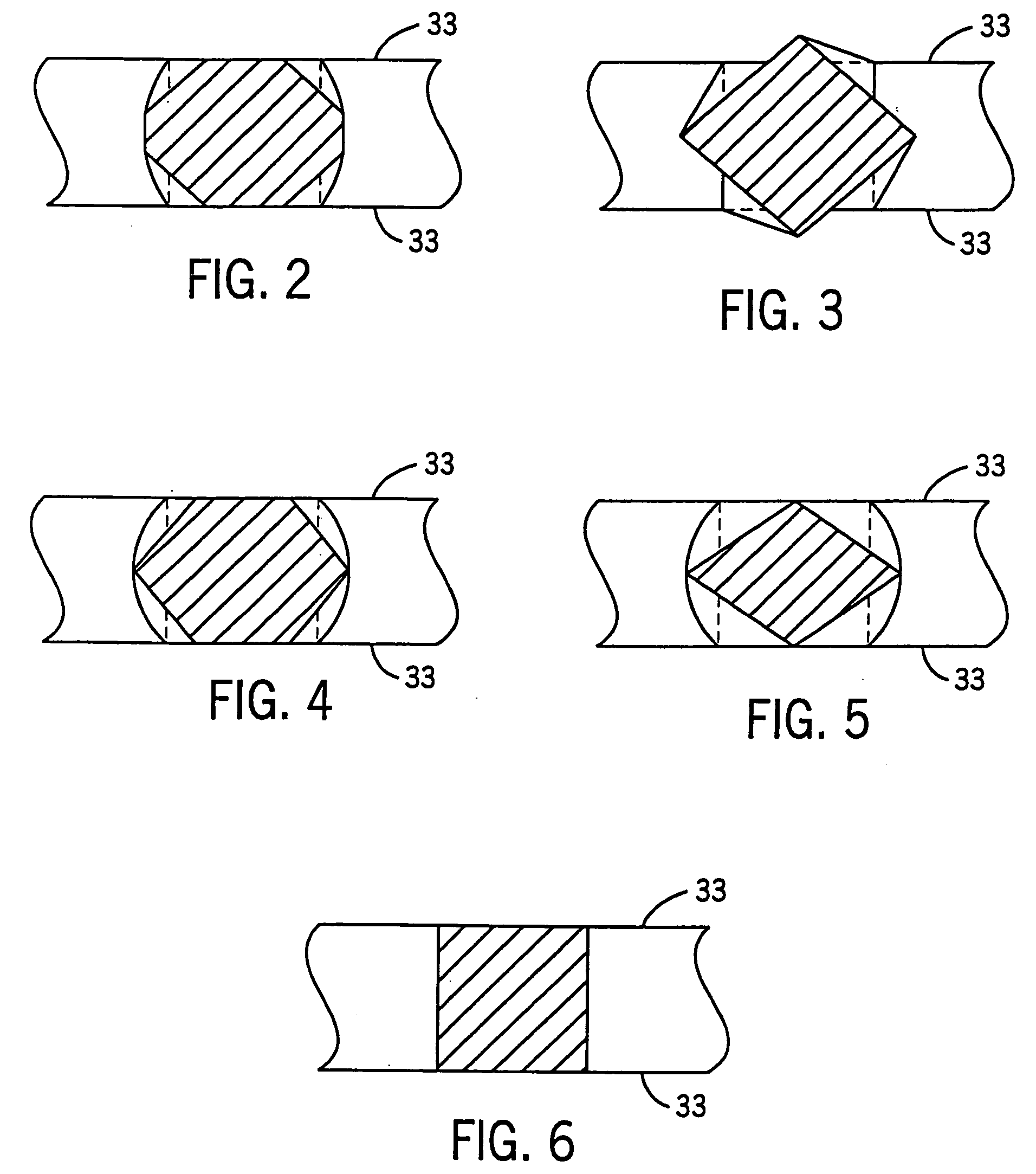
[0072] A continuous strip was prepared from a lead-alloy having the following composition: 0.0425 wt. % calcium, 0.925 wt. % tin, 0.013 wt. % aluminum, 0.0125 wt. % silver and balance lead. A series of interconnected battery grid shapes were then formed in the strip in a progressive punching operation, i.e., features were added to the battery grid through several punching operations. The battery grid wire sections of the strip were then processed in a coining station to coin the grid wires so that the grid wires had a cross-section similar to the grid wire cross-sections 90c in FIG. 4. The interconnected battery grids were then divided into individual grids. The grids were then pasted with a conventional battery paste and formed into battery cells. The battery cells were then cycled in accordance with the SAE J240 life test procedure at a temperature of 75° C. (167° F.) to measure the service life.

example 2

[0073] A continuous strip was prepared from a lead-alloy having the following composition: 0.0425 wt. % calcium, 0.925 wt. % tin, 0.013 wt. % aluminum, 0.0125 wt. % silver and balance lead. A series of interconnected battery grid shapes were then formed in the strip in a progressive punching operation, i.e., features were added to the battery grid through several punching operations. The battery grid wire sections of the strip were then processed in a coining station to coin the grid wires so that the grid wires had a cross-section similar to the grid wire cross-sections 90c in FIG. 4. The interconnected battery grids were then divided into individual grids. The grids were then hand dipped into a pot of molten 94 wt. % lead—6 wt. % tin coating alloy. The grids were dipped slowly into the melt until they bottomed out in the pot and then slowly withdrawn at the same rate for a total immersion time of about 2 seconds. The coating was uniform with no excess buildup on the grid wires or ...

example 3

[0074] A continuous strip was prepared from a lead-alloy having the following composition: 0.0425 wt. % calcium, 0.925 wt. % tin, 0.013 wt. % aluminum, 0.0125 wt. % silver and balance lead. A series of interconnected battery grid shapes were then formed in the strip in a progressive punching operation, i.e., features were added to the battery grid through several punching operations. The battery grid wire sections of the strip were then processed in a coining station to coin the grid wires so that the grid wires had a cross-section similar to the grid wire cross-sections 90c in FIG. 4. The interconnected battery grids were then divided into individual grids. The grids were then hand dipped into a pot of molten 94 wt.% lead—3 wt. % tin—3 wt. % antimony coating alloy. The grids were dipped slowly into the melt until they bottomed out in the pot and then slowly withdrawn at the same rate for a total immersion time of about 2 seconds. The coating was uniform with no excess buildup on th...


PUM

PropertyMeasurementUnit
weight percentaaaaaaaaaa

Abstract

A method of making a plurality of battery plates includes forming a strip including a plurality of battery grids. Each battery grid includes a grid network bordered by a frame element and includes a plurality of spaced apart grid wire elements. Each grid wire element has opposed ends joined to one of a plurality of nodes to define a plurality of open spaces in the grid network. The method also includes deforming at least a portion of a plurality of the grid wire elements such that the deformed grid wire elements have a first transverse cross-section at a point intermediate their opposed ends that differs from a second transverse cross-section taken at at least one of their opposed ends. The method also includes applying a lead alloy coating to the strip, applying battery paste to the strip, and cutting the strip to form a plurality of battery plates.

Description

CROSS-REFERENCE TO RELATED PATENT APPLICATIONS [0001] The present application is a divisional application under 35 U.S.C. § 121 of (and also expressly incorporates by reference herein in its entirety) the following related application: U.S. patent application Ser. No. 09 / 755,337 filed Jan. 5, 2001.BACKGROUND [0002] The present application relates to the modification of battery grids of the type used in lead-acid storage batteries, and more particularly, it relates to a modification of the surface finish of the battery grids of a lead-acid storage battery to improve paste adhesion and the service life of the battery. [0003] Lead-acid storage batteries typically comprise several cell elements which are encased in separate compartments of a container containing sulfuric acid electrolyte. Each cell element includes at least one positive plate, at least one negative plate, and a porous separator positioned between each positive and negative plate. The positive and negative plates each co...

Claims


Application Information

Patent Timeline
Patent Type & Authority Applications(United States)
IPC IPC(8): C22C11/06H01M4/20H01M4/66H01M4/68H01M4/73H01M4/74H01M4/84
CPCH01M4/20H01M4/667H01M4/685H01M4/73Y10T29/49115Y02E60/126Y10T29/10Y10T29/49108H01M4/745Y02E60/10H01M4/82
Inventor CHEN, YU-LIN
Owner CPS TECH HLDG LLC
Why Eureka
Try Eureka