Separator

a technology of separator and separator plate, which is applied in the field of separator, can solve the problems of high field capital expenditure and operational expenditure, reduce the commercial ceiling at which the field can be operated viably, and no longer commercially viable to operate the well, and achieve the effect of quick and efficient separation of multi-phase flow

Active Publication Date: 2005-07-14
ONESUBSEA IP UK LTD
View PDF36 Cites 21 Cited by
  • Summary
  • Abstract
  • Description
  • Claims
  • Application Information

AI Technical Summary

Benefits of technology

[0041] The present invention aims to overcome the problems associated with the prior art and to provide a separator which can quickly and efficiently separate multiphase flow into the individual component flows.
[0046] Thus, the present invention provides a rotational path through which the multiphase fluid is caused to flow and allows a large volume flow path to be achieved without requiring a large separation vessel. The separator of the present invention can be provided in a low snag resistant module and does not require a drilling installation operation.
[0054] Preferably, the separator further comprises a spiral conduit connected to at least one of the outlets, the conduit(s) having a smaller flow diameter than any of the annular tubular bores, thereby increasing the fluid velocity to enable further separation of the fluids into the desired phases.
[0059] Preferably, the separator further comprises one or more outlets from the spiral to allow for the further separation of lighter and heavier fluids.

Problems solved by technology

Overall, the current approach requires a complex field production system which has numerous pipelines, thus incurring a high field capital expenditure and operational expenditure.
This high expenditure reduces the commercial ceiling at which the field can be operated viably.
As the field matures and production declines, a level is reached at which considerable resources are left in place but at which it is no longer commercially viable to operate the wells.
Back pressure on the well reduces the production rate and brings on an early decline of the wells flowing life as the reservoir pressure at the bottom of the well must overcome the hydrostatic head and the pressure caused by friction.
The input of energy increases the lift cost of the oil from the well, thereby reducing the commercial viability of the well and, in some cases, the entire field.
Accordingly, and especially in deep water, the limited production rates, the early decline and the higher costs result in an increased investment requirement with a lower rate of return.
This ensures that small and medium sized fields cannot be exploited fully, if at all, using current practices.
When wells are at a considerable horizontal distance along the seabed from the surface production vessel, a number of significant problems such as slugging, hydrates, waxing and an increased back pressure are caused by the distance that the production fluid must travel.
In addition, using gas artificial lift in the well can exacerbate these problems causing pipelines to require higher specifications and larger diameters, thereby increasing the cost.
However, such multiphase pumps require additional energy which increases the cost of this approach.
The requirements for pumping this free gas are very different and, in many cases, opposite to those required for pumping liquid and therefore there is a design conflict and, at best, only a poor compromise can be achieved.
Large conventional tanks are no longer suitable and smaller tanks capable of withstanding high internal and / or external pressures have to be used.
The reduced size either reduces the volume throughput or several have to be used considerably increasing the complexity.
Although the separation is efficient, the volume throughput is limited by the constraining diameter and the length of the conductor.
The height required for a silo could lead to a high profile on the seabed and possible snagging problems.
The main disadvantage of these high g force separators for separating moving liquids in a fixed cyclone or helix compared with a stationary fluid in a centrifuge is the high shear stress forces which results in breaking down the droplet size, causing smaller droplets, even creating emulsions.

Method used


Image

  • Separator
  • Separator
  • Separator

Examples


Embodiment Construction

[0041] The present invention aims to overcome the problems associated with the prior art and to provide a separator which can quickly and efficiently separate multiphase flow into the individual component flows.

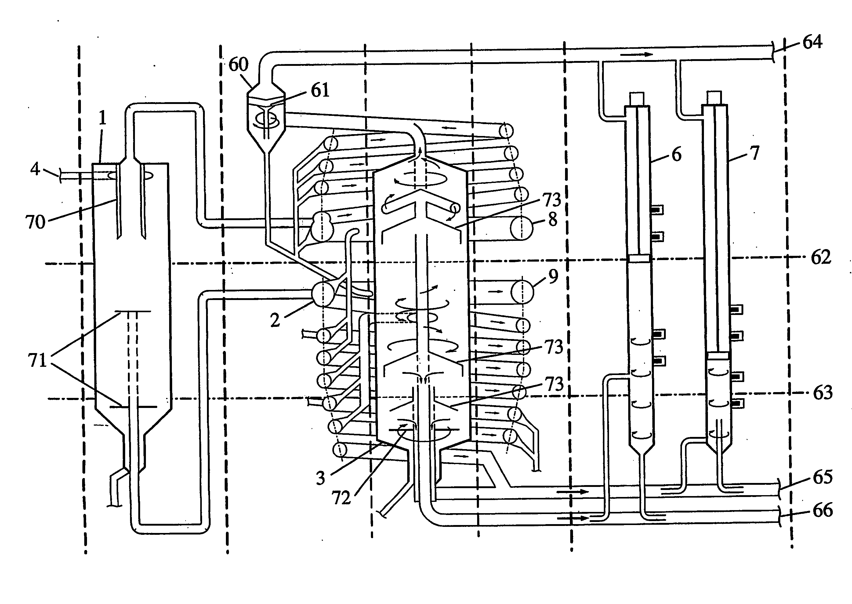
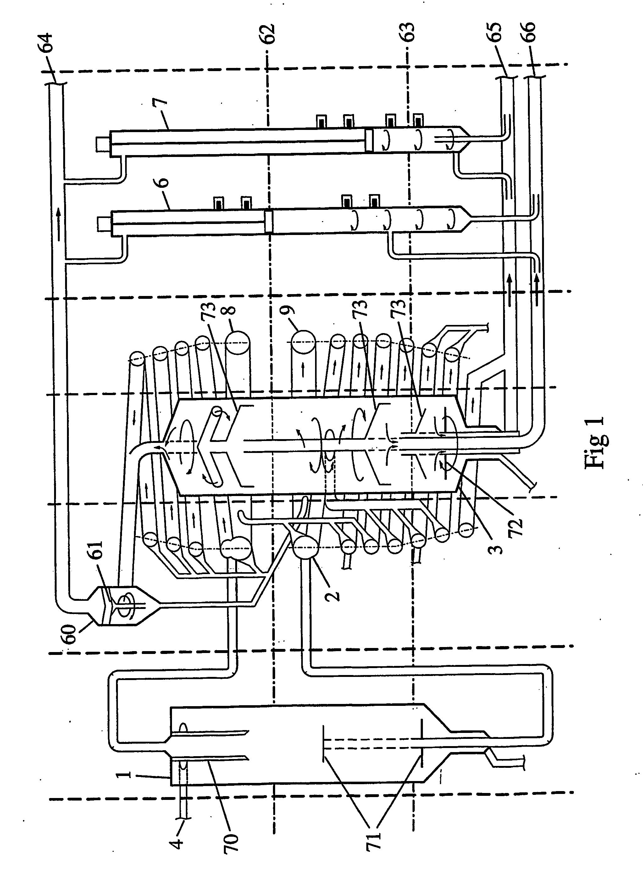
[0042] According to the present invention, there is provided a separator for separating multiphase fluid, the separator comprising: [0043] an inlet for a multiphase fluid; [0044] a plurality of outlets, at least one for each selected separated phase; [0045] a main annular tubular bore through which the multiphase fluid is caused to flow and to separate into lighter and heavier fluids, the bore having an outlet for each of the lighter and heavier fluids.

[0046] Thus, the present invention provides a rotational path through which the multiphase fluid is caused to flow and allows a large volume flow path to be achieved without requiring a large separation vessel. The separator of the present invention can be provided in a low snag resistant module and does not require a drillin...


PUM

PropertyMeasurementUnit
velocityaaaaaaaaaa
velocityaaaaaaaaaa
diameteraaaaaaaaaa

Abstract

A separator for separating multiphase flow, the separator comprising: an inlet for multiphase fluid; a plurality of outlets at least one for each selected separator phase; and a main annular tubular bore through which the multiphase flow is caused to flow and to separate into lighter and heavier fluids, the bore having an outlet for each of the lighter and heavier fluids.

Description

CROSS-REFERENCE TO RELATED APPLICATION [0001] This application is a National Phase entry of PCT Application No. PCT / GB03 / 01253 filed 24 Mar. 2003 which claims priority to EP Application No. 02252502.6 filed 8 Apr. 2002, both of which are incorporated herein by reference.BACKGROUND OF THE INVENTION [0002] This invention relates to a separator for separating multiphase flow and, in particular, a separator which can be utilised as part of the subsea assembly described in our co-pending European patent application entitled “Subsea Process Assembly” and filed on the same day (agent's ref: MJBO7O59EP), both hereby incorporated herein by reference. [0003] In general, the current practice for development of subsea hydrocarbon fields is on a macro field approach which uses a plurality of subsea wells connected through a subsea infrastructure, pipelines and risers to a surface process facility, such as a floating production vessel or a platform. In many locations, especially in remote areas, ...

Claims


Application Information

Patent Timeline
Patent Type & Authority Applications(United States)
IPC IPC(8): B01D17/00B01D17/038B01D21/00
CPCB01D17/00B01D21/2427B01D21/10B01D21/2411B01D17/0217B01D17/12
Inventor HOPPER, HANS PAUL
Owner ONESUBSEA IP UK LTD
Why Eureka
Try Eureka