Rotary powder compression molding machine

a molding machine and powder technology, applied in dough shaping, manufacturing tools, food shaping, etc., can solve the problems of remarkable wear of seals, difficult cleaning, and large revolving resistance of tool parts, and achieve the effect of preventing the decrease of air tightness of valves

Active Publication Date: 2005-07-14
KIKUSUI SEISAKUSHO LTD
View PDF3 Cites 11 Cited by
  • Summary
  • Abstract
  • Description
  • Claims
  • Application Information

AI Technical Summary

Benefits of technology

[0032] In this way, by using a reciprocating valve, to selectively communicate the first pooling container with the second pooling co...

Problems solved by technology

However, when employing such tool constructions, the revolving resistance of the tool parts becomes great, when the rocker valve is rotated.
This results in remarkable wear of the seals.
When such a situation occurs, the scattering of the powdery material within the housing interior becomes pervasive, and its cleaning becomes difficult.
In this ...

Method used


Image

  • Rotary powder compression molding machine
  • Rotary powder compression molding machine
  • Rotary powder compression molding machine

Examples


Embodiment Construction

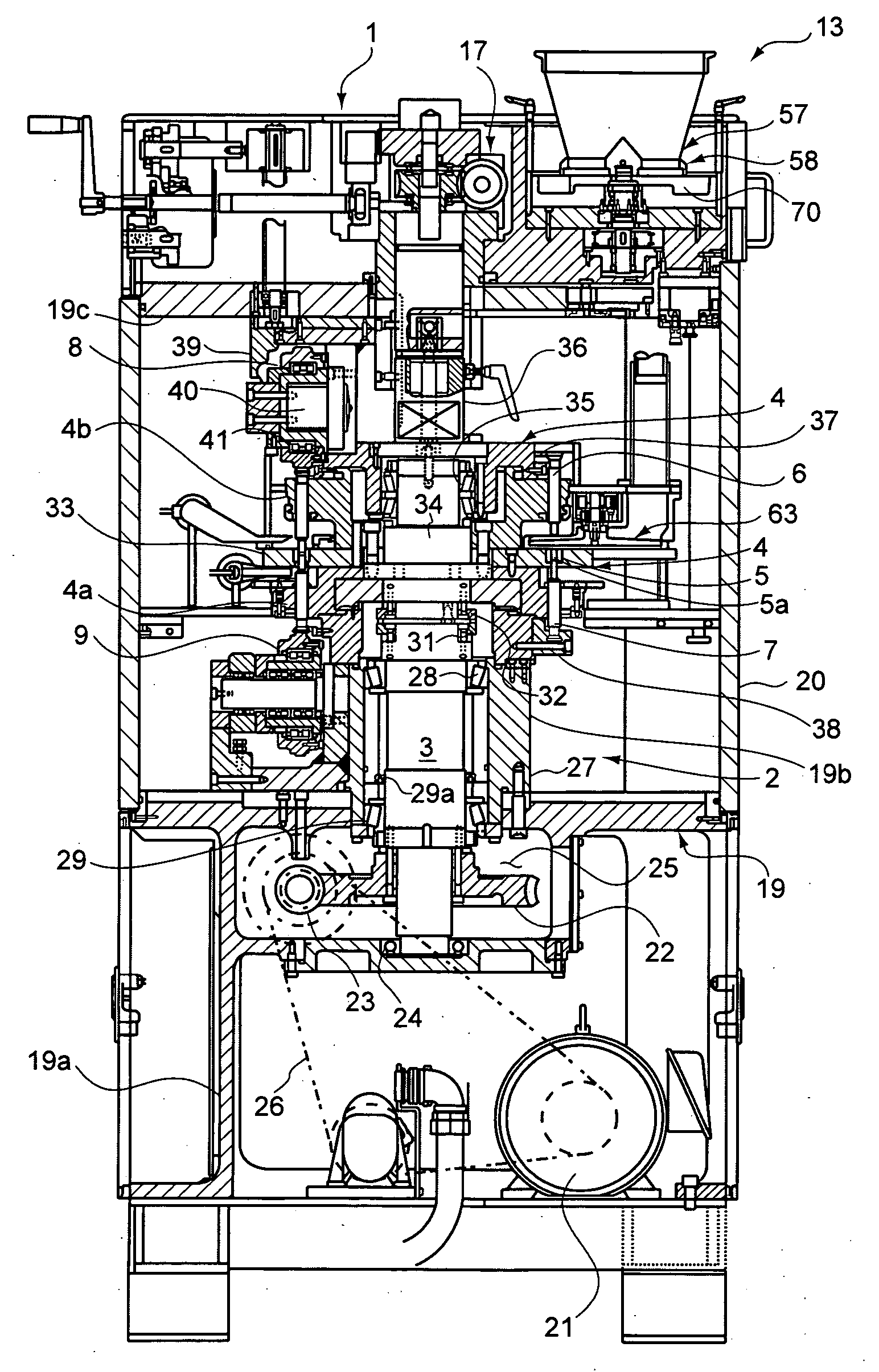
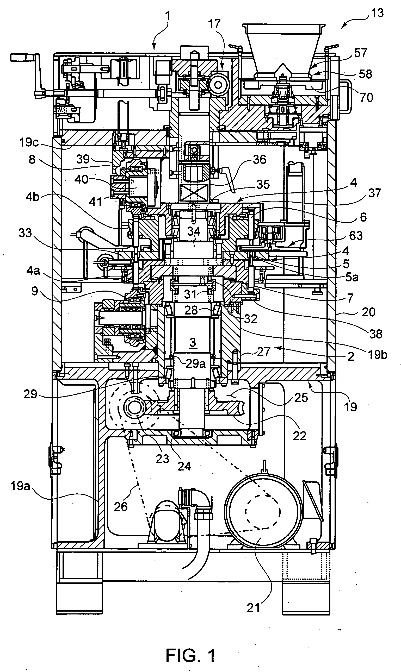
[0056] One embodiment of the present invention will be explained below, referring to FIGS. 1-11.

[0057]FIG. 1 is a longitudinal sectional drawing showing the rotary powder compression molding machine involved in the present embodiment. This powder compression molding machine has a housing 1 for cutting off the inside of the molding machine from the outside atmosphere. It also has a compression molding mechanism 2 provided in this housing 1, for compression molding, within the housing 1, a powdery material into a prescribed form.

[0058] As shown in FIG. 1, this compression molding mechanism 2 has, by means of a vertical shaft 3 within the housing 1 as the rotating axis, a rotary table 4 arranged to be horizontally rotatable. A plurality of dies having a die bore 5a is installed at a fixed pitch on the rotary table 4. Above and below each die 5 is an upper punch 6 and a lower punch 7, kept to be slidable in up-down directions. Additionally, an upper roller 8 for pushing the upper punc...


PUM

PropertyMeasurementUnit
Pressureaaaaaaaaaa

Abstract

[Problem to be Solved]An apparatus is provided for effectively preventing the scattering and the like of powder material, by maintaining a completely sealed condition, from the supply of the powdery material and the discharge of the molded articles to the cleaning of the interior.
[Means of Solving]Said housing 1 comprising, connected via a piping system 10, a vacuum device 11 for depressurizing said housing 1 interior; an atmosphere cut-off valve 12 installed on said piping system 10 for cutting off a piping interior atmosphere on said housing 1 side from a piping interior atmosphere on the vacuum device 11 side; a wetdown piping system 72 for wetting, within the atmosphere on the housing 1 side starting from said atmosphere cut-off valve 12, a compression molding mechanism 2 as well as powdery material stuck to the inside of said housing 1; and an outside air introduction mechanism 15 installed on said housing 1 for opening up an airtight condition of the housing 1.

Description

CROSS REFERENCE TO RELATED APPLICATIONS [0001] This application claims priority under 35 U.S.C. 119 based upon PCT Patent Application Serial No. PCT / JP03 / 12683, filed on Oct. 2, 2003. The entire disclosure of the aforesaid applications is incorporated herein by reference.BACKGROUND OF THE INVENTION [0002] 1. Field of the Invention [0003] The present invention relates to a powder compression molding machine for producing powder compression molded articles such as drugs, foods and electronic components. [0004] 2. Description of the Prior Art [0005] Conventional rotary powder compression molding machines have a rotary table, arranged to rotate horizontally by means of a vertical shaft within a housing. A plurality of dies are arranged at a fixed pitch on this rotary table. Above and below each die is kept an upper punch and a lower punch enabled to slide up and down. The upper punch and lower punch, which have their punch points inserted within the dies, are passed between an upper rol...

Claims


Application Information

Patent Timeline
IPC IPC(8): B29C31/02B29C43/04B29C43/08B29C43/34
CPCB29C31/02B29C43/34B29C43/08B30B11/08B30B15/0082
Inventor SHIMADA, KEIJIHARADA, KENJI
Owner KIKUSUI SEISAKUSHO LTD
Why Eureka
Try Eureka