ADC with digital error correction

a digital error correction and error correction technology, applied in the field of analog to digital converters, can solve the problems of inability to strictly match the response of individual adcs, inability to find a limitation, and inability to achieve the effect of reducing the error rate of the acquired signal,

Active Publication Date: 2005-07-14
KEYSIGHT TECH
View PDF14 Cites 18 Cited by
  • Summary
  • Abstract
  • Description
  • Claims
  • Application Information

AI Technical Summary

Problems solved by technology

However, this technique finds a limitation in the fact that the individual responses of the individual ADCs, like for example Gain, Delay, Nonlinearity or Offset, can never be strictly identical.
This mismatch is reflected in unwanted distortions of the acquired signal, which manifest themselves in the frequency domain as spurious spectral com

Method used


Image

  • ADC with digital error correction
  • ADC with digital error correction
  • ADC with digital error correction

Examples


Embodiment Construction

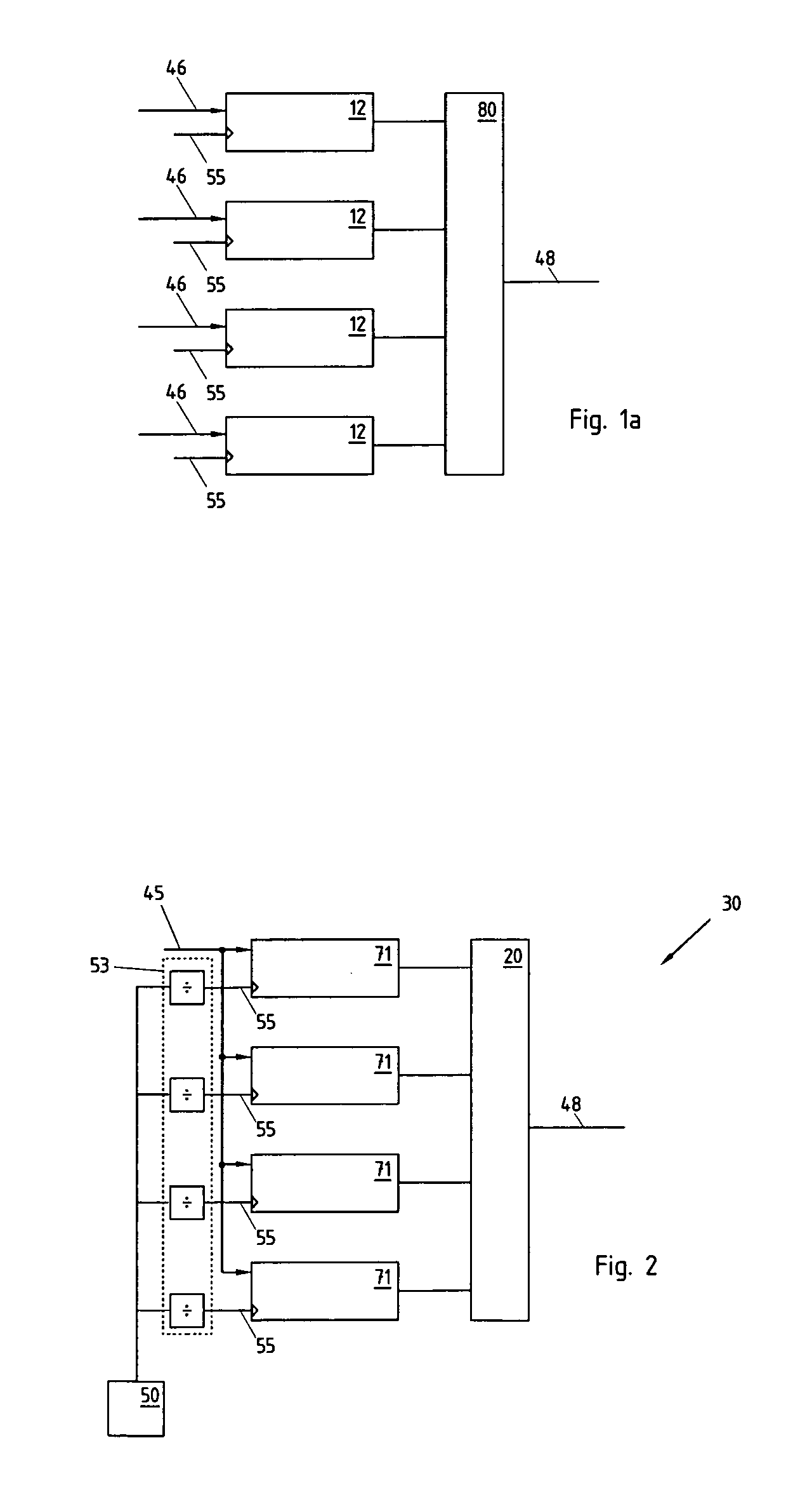
[0024]FIG. 2 schematically represents an interleaved ADC according to the present invention. The ADC 30 comprises a clock generator 50 having a frequency F, for synchronizing the various operations of the ADC. The clock generator may include a local clock oscillator, not represented, or generate a clock signal in dependence on an external clock input, for example if the ADC is an element of a multi-channel acquisition system. An analogue signal, whose amplitude must be digitized, is present at an analogue input 45. Although not represented on this figure, it is to be understood that the device of the invention may also include a variety of analogue signal conditioning means, like for example filters, anti-aliasing filters, voltage protection networks, attenuators, impedance matching circuits, amplifiers or the like, and that the analogue signal may be a voltage signal as well as a current signal.

[0025] The analogue signal 45 is fed to the inputs of a plurality of N individual ADC 7...


PUM


Abstract

Interleaved Analogue to Digital converter, comprising a plurality of individual ADCs (71). A digital filter stage (20) is used for equalizing the responses of the individual ADCs, and comprises a FIR filter in which the coefficient table is cyclically reloaded between ADCs' samples, in order to reduce the number of multipliers required.

Description

REFERENCE DATA [0001] This application claims priority from European Patent Application No. EP03104679.0 filed on Dec. 12, 2003, the contents whereof are hereby incorporated by reference. FIELD OF THE INVENTION [0002] The present patent application relates to an Analogue to Digital Converter (ADC), and in particular to an ADC including a plurality of time-interleaved converters for increasing the overall conversion rate and a correction scheme for compensating the errors which might arise by mismatches in individual converters. DESCRIPTION OF RELATED ART [0003] In data acquisition systems using Analogue to Digital Converters (ADC), a technique of time-interleaving several identical ADC of lower conversion rate is often used to increase the overall conversion rate. By employing a large number of individual slow ADCs, it is possible to achieve extremely high overall conversion speeds. [0004] However, this technique finds a limitation in the fact that the individual responses of the in...

Claims


Application Information

Patent Timeline
IPC IPC(8): H03H17/06H03M1/06H03M1/08H03M1/12
CPCH03H17/0226H03H17/06H03M1/1215H03M1/0836H03M1/0626
Inventor ADAMS, NEIL
Owner KEYSIGHT TECH
Why Eureka
Try Eureka