Internal combustion engine of compressing and auto-igniting air-fuel mixture and method of controlling such internal combustion engine

a technology of air-fuel mixture and internal combustion engine, which is applied in the direction of machines/engines, electrical control, exhaust treatment electric control, etc., can solve the problems of preventing the occurrence of severe knocking, affecting the efficiency of combustion engines, so as to achieve effective control of the timing of auto ignition

Active Publication Date: 2005-07-21
TOYOTA JIDOSHA KK
View PDF18 Cites 48 Cited by
  • Summary
  • Abstract
  • Description
  • Claims
  • Application Information

AI Technical Summary

Benefits of technology

[0010] The object of the present invention is thus to solve the drawbacks of the prior art techniques described above and to provide a technique of effectively controlling the timing of auto ignition of an air-fuel mixture in an internal combustion engine that adopts the premix compression ignition combustion system.

Problems solved by technology

Under some driving conditions of the internal combustion engine, the timing of auto-igniting the air-fuel mixture is too early, and the air-fuel mixture is undesirably auto-ignited in the course of compression.
This leads to the occurrence of severe knocking.
Such prior art technique, however, has difficulties in reliably controlling the timing of auto ignition of the air-fuel mixture and in preventing the occurrence of knocking.
The decrease in concentration of the fuel in the whole combustion chamber naturally lengthens the auto ignition delay time and prevents auto ignition of the air-fuel mixture prior to ignition.
The excessively low concentration of the fuel, however, makes it hard to ignite the air-fuel mixture.

Method used


Image

  • Internal combustion engine of compressing and auto-igniting air-fuel mixture and method of controlling such internal combustion engine
  • Internal combustion engine of compressing and auto-igniting air-fuel mixture and method of controlling such internal combustion engine
  • Internal combustion engine of compressing and auto-igniting air-fuel mixture and method of controlling such internal combustion engine

Examples


second embodiment

B. Second Embodiment

[0083] B-1. Structure of System

[0084] B-2. Combustion Control of Air-Fuel Mixture in Second Embodiment

first embodiment

A. First Embodiment

A-1. Structure of System

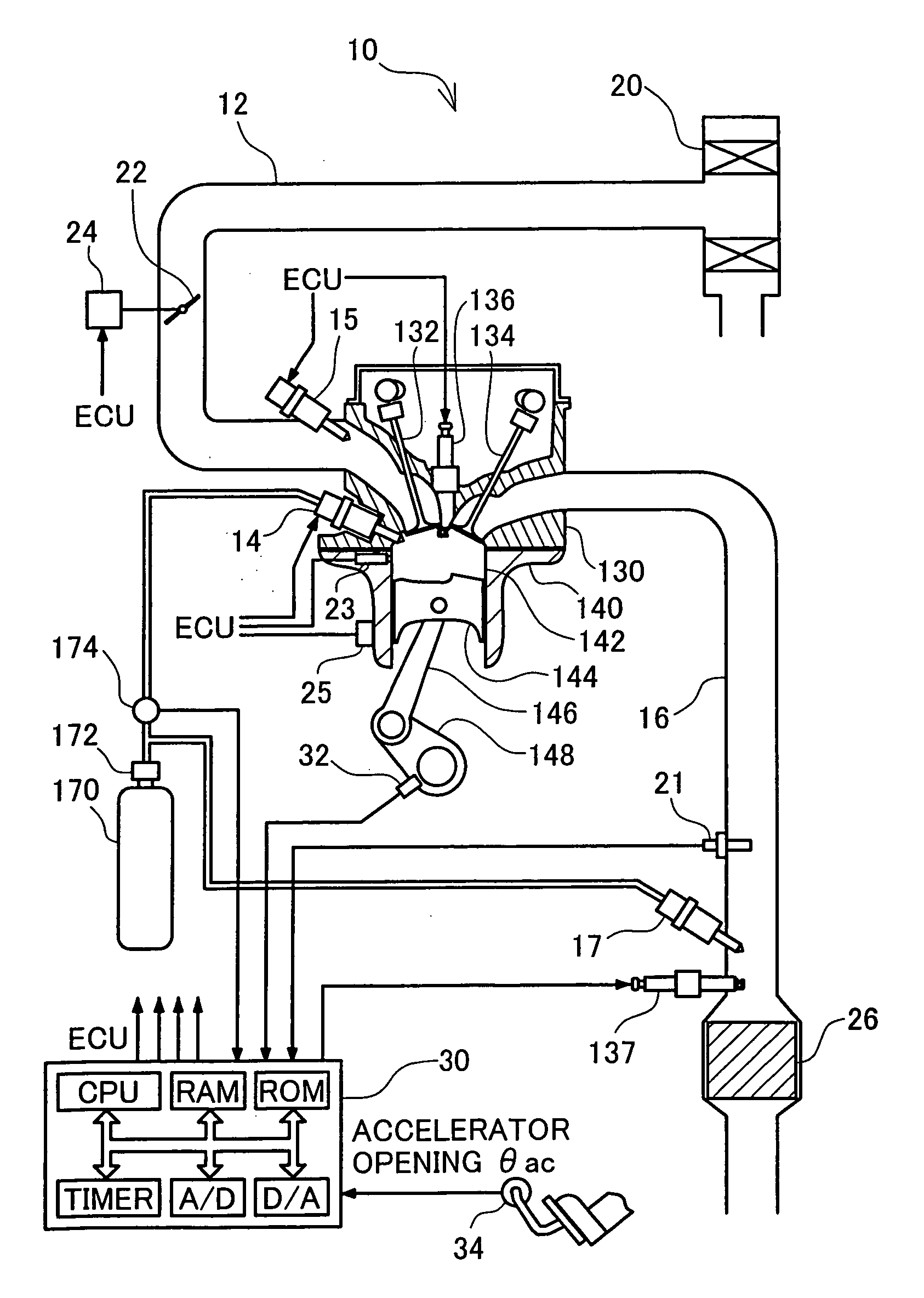
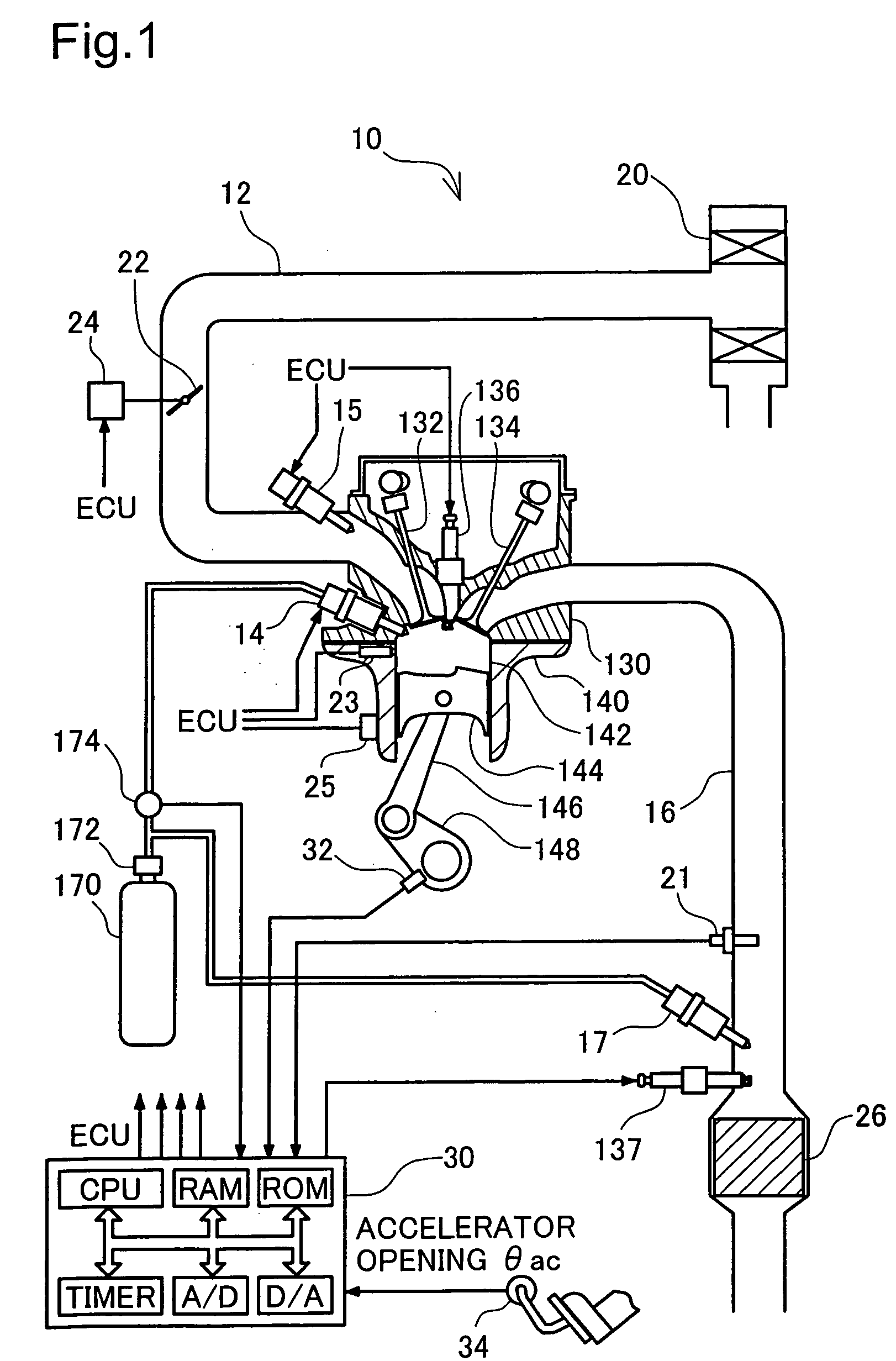
[0085]FIG. 1 conceptually illustrates the structure of an engine 10 in a first embodiment of the present invention that adopts the premix compression ignition combustion system. The engine 10 of the first embodiment is a 4-cycle engine that makes the air-fuel mixture combusted in a combustion chamber to output power through repetition of four cycles of air intake, compression, expansion, and exhaust. For distinct illustration of the structure of the engine 10, the cross section is taken on a substantial center of the combustion chamber in FIG. 1. A main body of the engine 10 has a cylinder head 130 mounted on an upper portion of a cylinder block 140. A cylindrical cylinder 142 is arranged inside the cylinder block 140, and a piston 144 vertically slides in the cylinder 142. The space defined by the cylinder 142, the piston 144, and the lower face of the cylinder head 130 forms a combustion chamber.

[0086] The piston 144 is connected to a ...

first modified example

(a) FIRST MODIFIED EXAMPLE

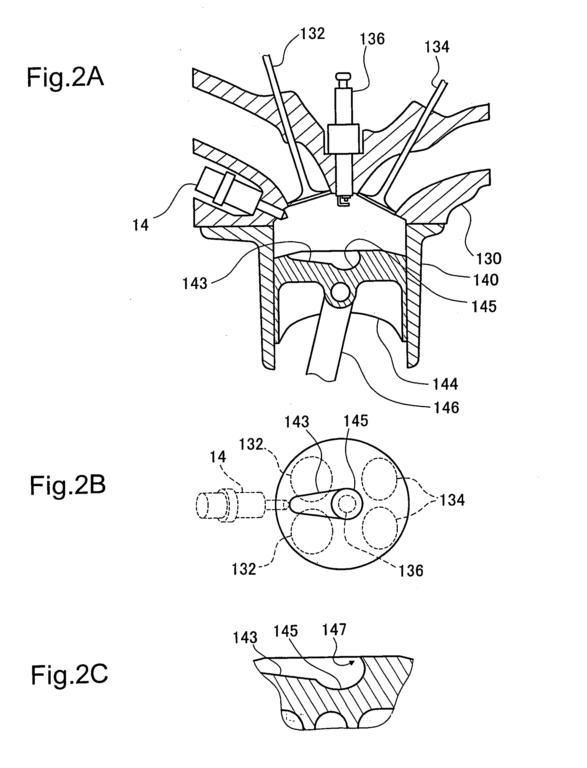
[0157]FIGS. 14A and 14B illustrate the structure of a combustion chamber in another engine in a first modified example of the first embodiment. FIG. 14A is a sectional view of the combustion chamber, and FIG. 14B is a top view showing the top face of the piston 144 seen from the cylinder head 130. In the structure of the first embodiment described above, the fuel injection valve 15 for injection of gasoline is disposed in the intake conduit 12, and the fuel injection valve 14 for injection of hydrogen gas is disposed in the combustion chamber. In the structure of the first modified example, on the other hand, a fuel injection valve 19 for injection of gasoline and the fuel injection valve 14 for injection of hydrogen gas are disposed in the combustion chamber. Both gasoline and hydrogen gas are thus directly injected into the combustion chamber.

[0158] In the structure of direct injection of gasoline into the combustion chamber, gasoline is injected at a pr...


PUM


Abstract

The technique of the present invention produces a first fuel-air mixture containing a first fuel and the air at a specific ratio, which does not allow for auto ignition of the first fuel-air mixture by simple compression, in a combustion chamber. The technique then injects a second fuel, which has a higher octane value than that of the first fuel, into a partial area of the combustion chamber, so as to produce a second fuel-air mixture. The technique ignites the second fuel-air mixture for combustion, so as to compress and auto-ignite the first fuel-air mixture. The second fuel has the higher octane value, so that a combustion start timing of the second fuel-air mixture is reliably regulated by ignition. Namely the technique positively controls the timing of auto ignition of the first fuel-air mixture. Setting an adequate value to the ignition timing thus effectively prevents the occurrence of knocking in an internal combustion engine that adopts a premix compression ignition combustion system.

Description

BACKGROUND OF THE INVENTION [0001] 1. Field of the Invention [0002] The present invention relates to a technique of compressing and auto-igniting an air-fuel mixture of a fuel and the air in a combustion chamber and thereby taking out power. More specifically, the invention pertains to a technique of controlling auto ignition of the air-fuel mixture to take out power with a high efficiency, while effectively reducing emission of air pollutants through combustion. [0003] 2. Description of the Related Art [0004] Internal combustion engines produce large power by relatively small-sized bodies and are thus widely used as power sources of diverse transportation devices like automobiles, ships, and aircraft as well as stationary power sources in factories. The operation principle of such internal combustion engines makes a fuel subjected to combustion in a combustion chamber, converts a pressure produced through the combustion into a mechanical work, and outputs the converted mechanical w...

Claims


Application Information

Patent Timeline
Patent Type & Authority Applications(United States)
IPC IPC(8): F02P5/152F01N3/20F01N3/24F01N3/36F02B1/12F02B3/06F02B7/02F02B11/00F02B23/10F02B29/04F02B75/12F02D13/02F02D19/08F02D23/02F02D41/00F02D41/02F02D41/30F02D43/00F02M25/10F02P5/153
CPCF02B1/12Y02T10/36F02B7/02F02B23/101F02B23/104F02B29/0406F02B2075/125F02D13/0215F02D19/081F02D41/0025F02D41/3041F02D41/3058F02D2250/18F02D2400/02F02D2400/04F02M25/10Y02T10/18Y02T10/123F02D19/061F02D19/0644F02D19/0655F02D19/0689F02D19/0692F02B3/06Y02T10/12Y02T10/30
Inventor KOBAYASHI, TATSUO
Owner TOYOTA JIDOSHA KK
Why Eureka
Try Eureka