High-pressure delivery system for ultra high purity liquid carbon dioxide

Inactive Publication Date: 2005-07-21
AIR PROD & CHEM INC
View PDF8 Cites 10 Cited by
  • Summary
  • Abstract
  • Description
  • Claims
  • Application Information

AI Technical Summary

Benefits of technology

[0022] The FIGURE is a flow diagram of a combined pump free and recycle system for the delivery of high-p

Problems solved by technology

However, pumping liquid carbon dioxide to a high pressure can introduce impuriti

Method used


Image

  • High-pressure delivery system for ultra high purity liquid carbon dioxide
  • High-pressure delivery system for ultra high purity liquid carbon dioxide

Examples


Embodiment Construction

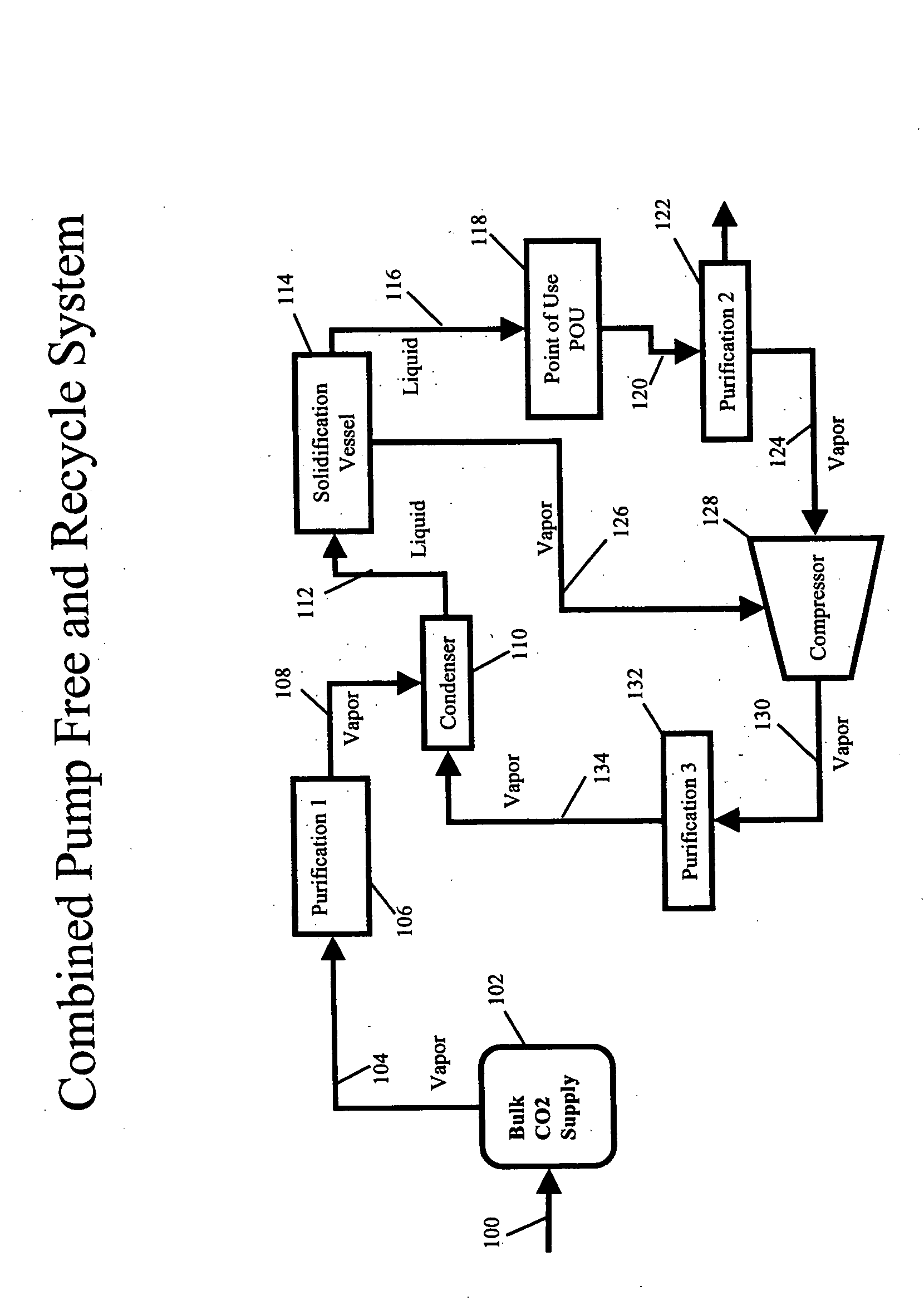
[0023] To facilitate an understanding of the basic process, reference is made to the drawing.

[0024] The FIGURE describes an onsite system for the pump free delivery of ultra high purity liquid carbon dioxide to a point of use and the recovery of the spent carbon dioxide.

[0025] In the general process, a stream of liquid carbon dioxide at initial process pressure and temperature parameters, for example, a liquid carbon dioxide process pressure of 300 psig and temperature of −5° F. is delivered via line 100 to bulk CO2 supply tank 102. Carbon dioxide then is removed from bulk CO2 supply tank 102 through line 104 and charged to purification system 106 to remove contaminants normally present in bulk CO2 deliveries. (Semiconductor processes, for example, require higher purities than afforded in industrial grade bulk delivery CO2.) Purification of the feed may require different methods, e.g., filtration, distillation, adsorption and the like to achieve the desired carbon dioxide purity r...


PUM

PropertyMeasurementUnit
Pressureaaaaaaaaaa
Temperatureaaaaaaaaaa
Pressureaaaaaaaaaa

Abstract

This invention relates to an improvement in a process and apparatus for delivering ultra high purity liquid carbon dioxide to a point of use at pressures above ambient without pumping. In the process a high purity carbon dioxide feed is charged to a vessel and at least partially solidified. Once filled, the slush or solid is isochorically heated, i.e., heated at constant vessel volume whereby the solid phase carbon dioxide is converted to a liquid. Liquid, then, is withdrawn from the vessel at a desired pressure at a rate at which the solid phase carbon dioxide is converted to a liquid. The improvement resides in effecting partial solidification and recycle of carbon dioxide.

Description

CROSS-REFERENCE TO RELATED APPLICATIONS [0001] This application is related to U.S. Ser. No. 10 / 353,188 having a filing date of Jan. 28, 2003 and U.S. Ser. No. 10 / 753,315 having a filing date of Jan. 9, 2004, the subject matter of both companion applications incorporated by reference.BACKGROUND OF THE INVENTION [0002] Highly pressurized, ultra high pure liquid carbon dioxide is required for a variety of industrial processes. For example, some of the evolving applications in the electronic industry demand the use of supercritical carbon dioxide at high flow rates and high pressures. Other applications, such as photo-resist removal, deposition, lithography, etc, require ultra high purity (UHP) liquid carbon dioxide delivered to a point of use (POU) in pressure range from 2,000 psig to 10,000 psig. The latter depends on many factors for example, specifics of an application, tool design, process philosophy, etc. [0003] One of the methods for achieving high pressure carbon dioxide has bee...

Claims


Application Information

Patent Timeline
IPC IPC(8): B01D9/04B25J1/00C02F1/22C01B32/50F17C5/04F17C5/06F17C7/00F17C9/02F17D1/08F25J1/00G05D16/00H01L21/02
CPCF17C5/04Y10S62/928F17C9/02F17C2221/013F17C2221/05F17C2223/0123F17C2223/0153F17C2223/033F17C2225/0115F17C2225/0123F17C2225/0153F17C2225/035F17C2227/0302F17C2227/0337F17C2227/0388F17C2250/01F17C2260/044F17C2265/015F17C2270/0518F17C5/06A61M1/08A61M2205/0216
Inventor GERSHTEIN, VLADIMIR YLIY
Owner AIR PROD & CHEM INC
Why Eureka
Try Eureka