Wallless monolith columns for chromatography

Inactive Publication Date: 2005-07-21
ARCHIDEX
View PDF4 Cites 26 Cited by
  • Summary
  • Abstract
  • Description
  • Claims
  • Application Information

AI Technical Summary

Benefits of technology

[0010] Another objective is to provide a monolith column that elimi

Problems solved by technology

Although the encasing of thermoplastic on to the monolith rod is tight, it still leaves “just a small dead space” at the junction of the thermoplastic wrap and the monolith rod.
When a mixture is separated in the column, it is eluted into bands of funnel shape by the influence of wall effect, severely affecting the resolution.
Several factors cause inferior cladding.
However, the interior surface of a cladding tube is mi

Method used


Image

  • Wallless monolith columns for chromatography
  • Wallless monolith columns for chromatography
  • Wallless monolith columns for chromatography

Examples


example 1

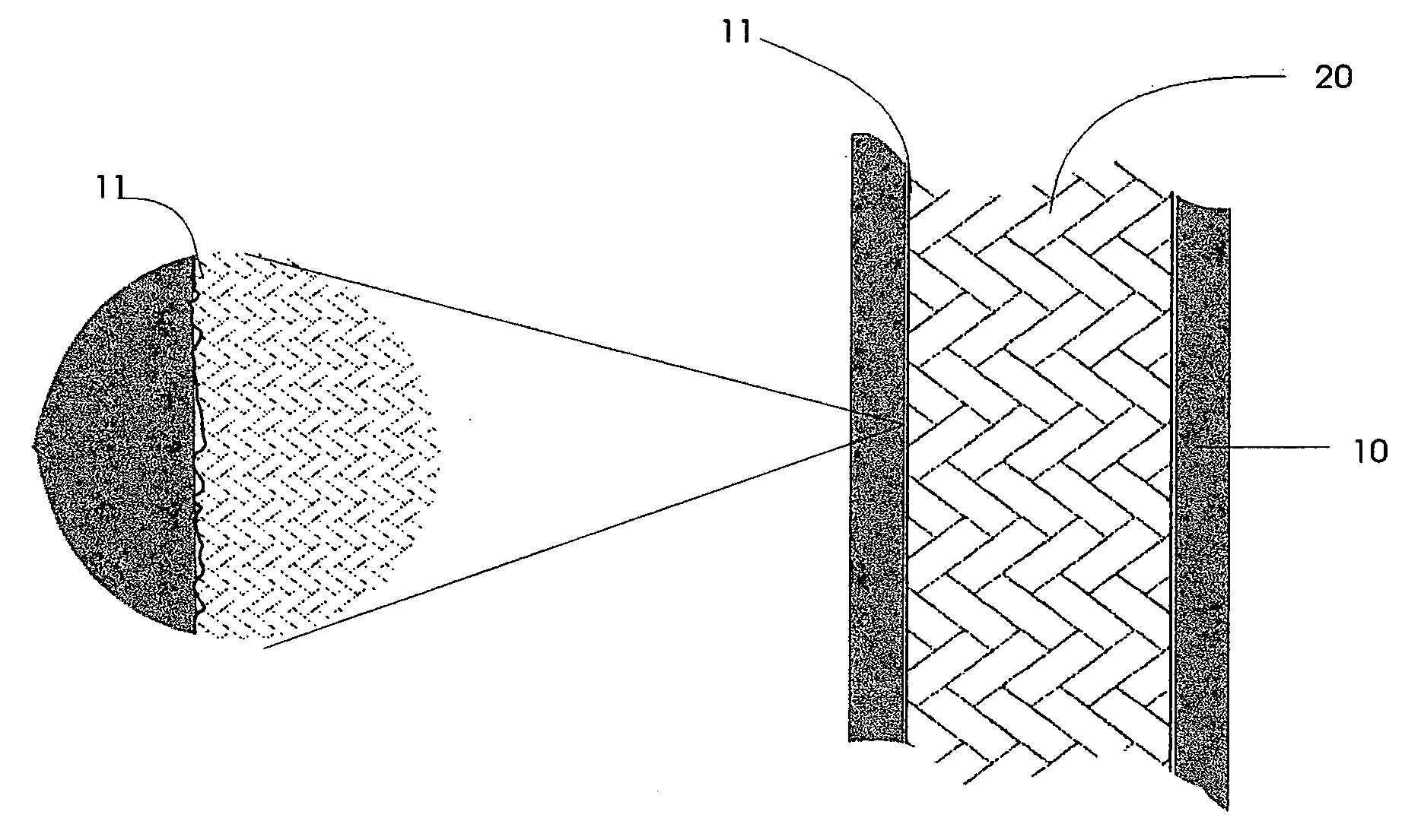
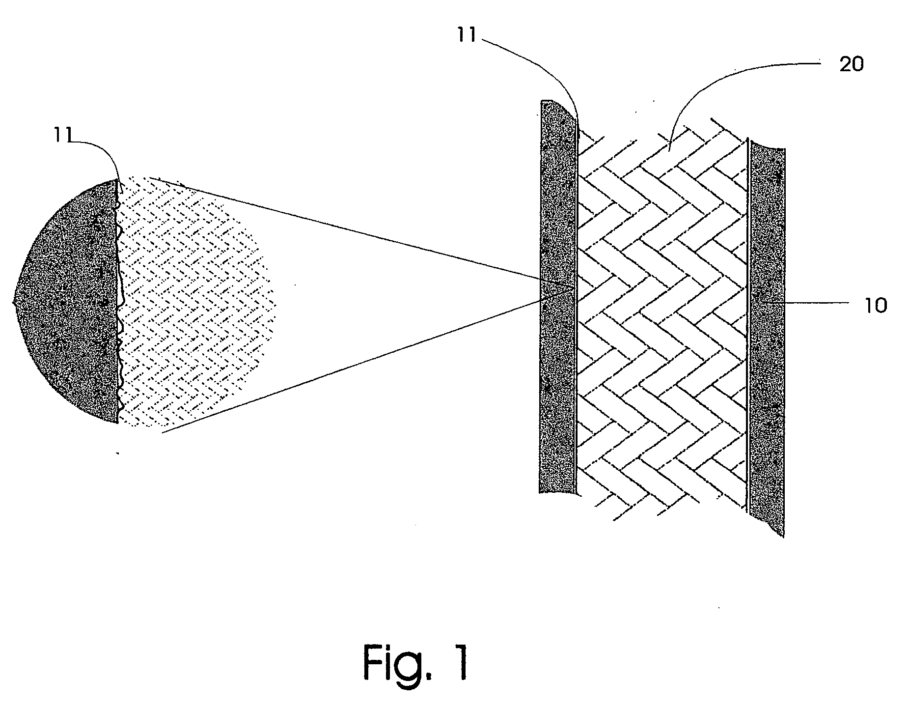
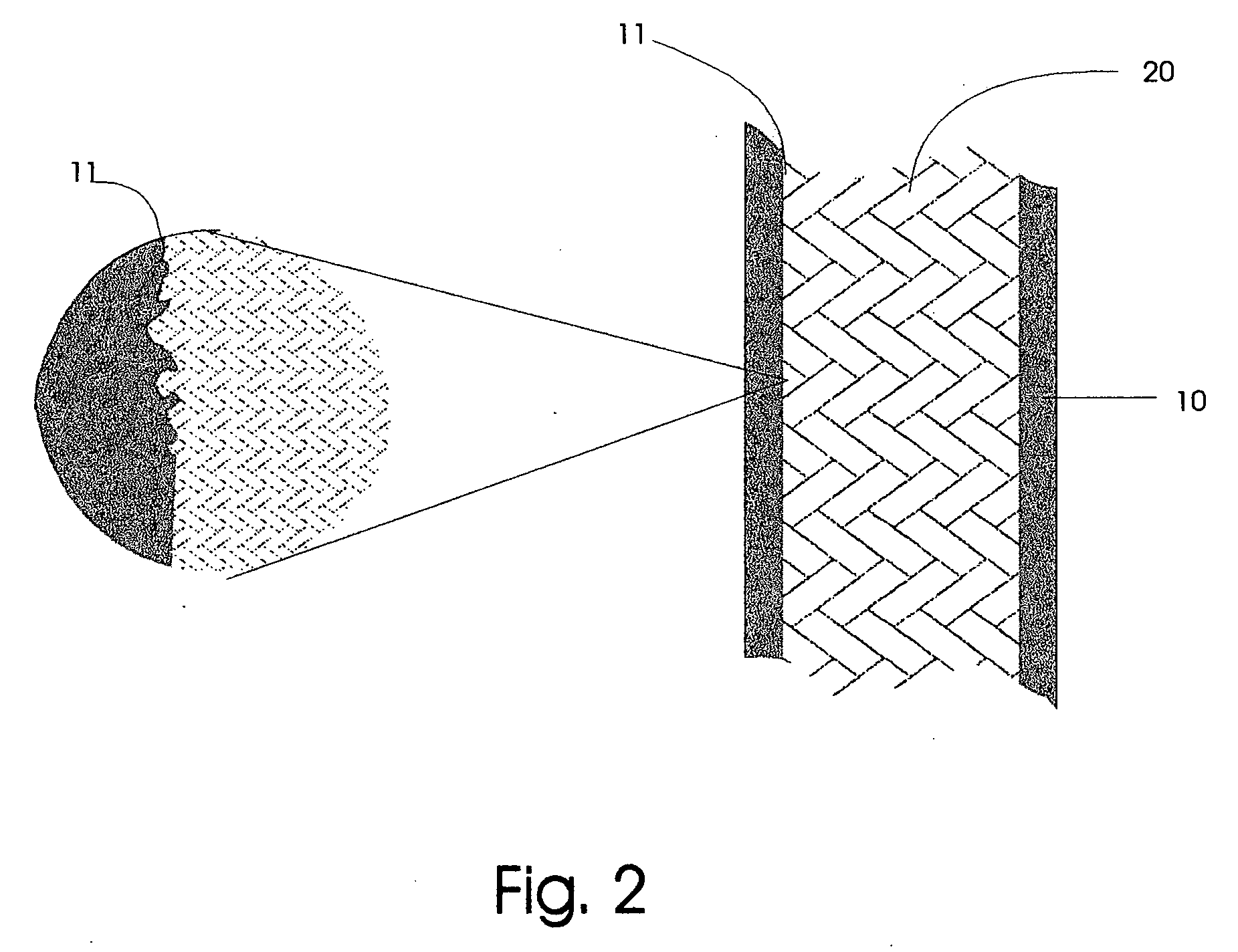
[0024] A silica rod (2.8 mm×100 mm, OD×Length) was inserted into a polyethylene tube (0.32 mm×100 mm, ID×Length). One end of the tube was sealed and the other end was connected to a vacuum pump. After applying vacuum for 10 minutes, the tube was immersed into an oil bath of 140 degree Celsius and kept in the bath till the tube turned to melting state. The tube was then removed away from the bath and cooled to room temperature. The section containing silica monolith rod was cut into a column of 80 mm length and was tested for its structure and chromatographic behavior.

[0025] The cross section of the column showed that the rod was tightly surrounded by the tube and there were no dead spaces between the rod and the tube. When the rod material was removed from the tube and the tube was thoroughly washed, a thin layer of rod material still remained in the interior wall of the tube and could not be washed away, showing the rod exterior surface was permanently intercalated into the tubing...

example 2

[0027] A silica rod (2.8 mm×100 mm, OD×Length) was inserted into a polyethylene tube (0.32 mm×100 mm, ID×Length). Both ends were connected to a vacuum pump and the rod was in the central section of the tube. After applying vacuum for 10 minutes, the section with the rod was immersed into an oil bath of 140 degree Celsius and kept in the bath till the tube turned to melting state. The tube was removed from the bath and cooled to room temperature. The section containing silica monolith rod was cut into a column of 80 mm length and was tested for its structure and chromatographic behavior.

[0028] The cross section of the column showed that the rod was tightly surrounded by the tube and there were no dead spaces between the rod and the tube. When the rod material was removed from the tube and the tube was thoroughly washed, a thin layer of rod material still remained in the interior wall of the tube and could not be washed away, showing the rod exterior surface was permanently intercala...

example 3

[0030] A silica rod (2.8 mm×100 mm, OD×Length) was inserted into a polyethylene tube (0.32 mm×100 mm, ID×Length). The rod was in the central section of the tube. The tube sealed into a tubular chamber with both ends exposed to atmosphere. The tubular chamber was filled with oil and a 4-psi pressure was applied to the oil in the chamber. The oil bath was heated to 140 degree Celsius and kept at this temperature till the tube turned to melting state (about 5 minutes). The oil in the chamber was cooled to room temperature and the pressure to the oil was then released. The rod was cladded in the tube after the process. The section containing silica monolith rod was cut into a column of 80 mm length and was tested for its structure and chromatographic behavior.

[0031] The cross section of the column showed that the rod was tightly surrounded by the tube and there were no dead spaces between the rod and the tube. When the rod material was removed from the tube and the tube was thoroughly ...


PUM

PropertyMeasurementUnit
Pressureaaaaaaaaaa
Massaaaaaaaaaa

Abstract

A monolith column for chromatography comprising a monolith rod encased with a tubular structure wherein the mass of the interior surface layer of said tubular structure intercalate by an encasing process into the surface layer of said monolith rod through the micro-cavities of said surface layer of said monolith rod, forming a hybrid layer shared by both said monolith rod and said tubular structure.

Description

PRIORITY CLAIM [0001] This application claims benefit of priority of U.S. Provisional Application Ser. No. 60 / 537,066 filed on Jan. 16, 2004 titled “Wallless Monolith Columns For Chromatography”.FIELD OF THE INVENTION [0002] The present invention relates to a monolithic column for liquid chromatography. BACKGROUND [0003] A monolith column refers to a continuous porous rod for chromatographic separation. The rod is cladded in a tube to guide fluid flow. For separation, the rod should be tightly cladded by the tube so that there would be no space in-between the exterior of the rod and the interior of the tube. In one prior art, the rod is inserted in a heat-shrinkable plastic tube that wraps the rod by heating (H. Minakuchi et al. J. Chromatography. A 762 (1997) 135-146). Though the process minimizes the space in-between the tube and the rod, the space has not been eliminated. FIG. 1 illustrates the structure of a monolith column of the prior art. The column contains a tube 10, a mono...

Claims


Application Information

Patent Timeline
IPC IPC(8): B01D15/22B01J20/28B01J20/282B01J20/283C02F1/28G01N30/52G01N30/60
CPCB01D15/22B01J20/28042B01J20/282B01J20/283B01J2220/58G01N2030/528B01J2220/82G01N30/6069
Inventor MA, QI-FENG
Owner ARCHIDEX
Why Eureka
Try Eureka