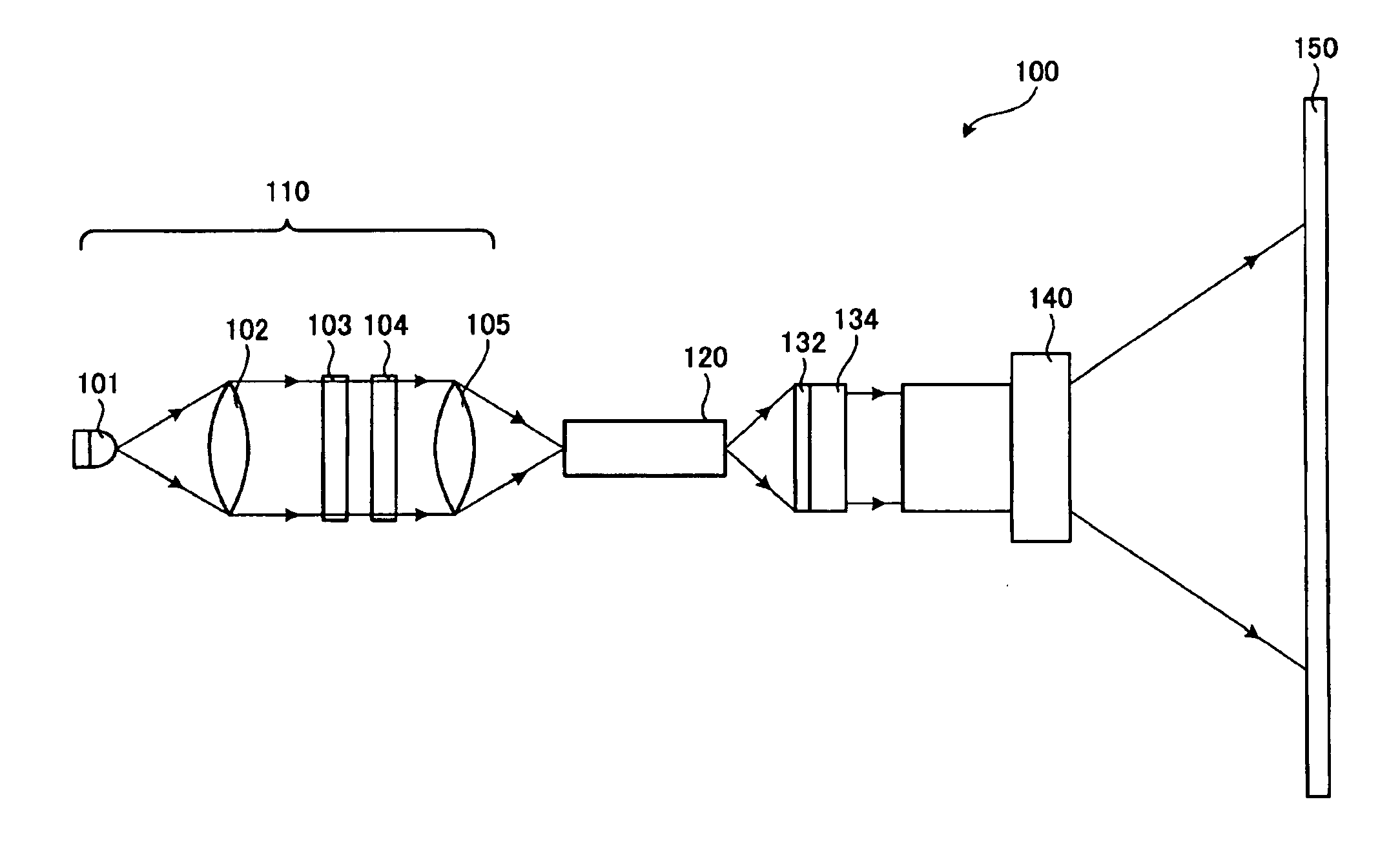
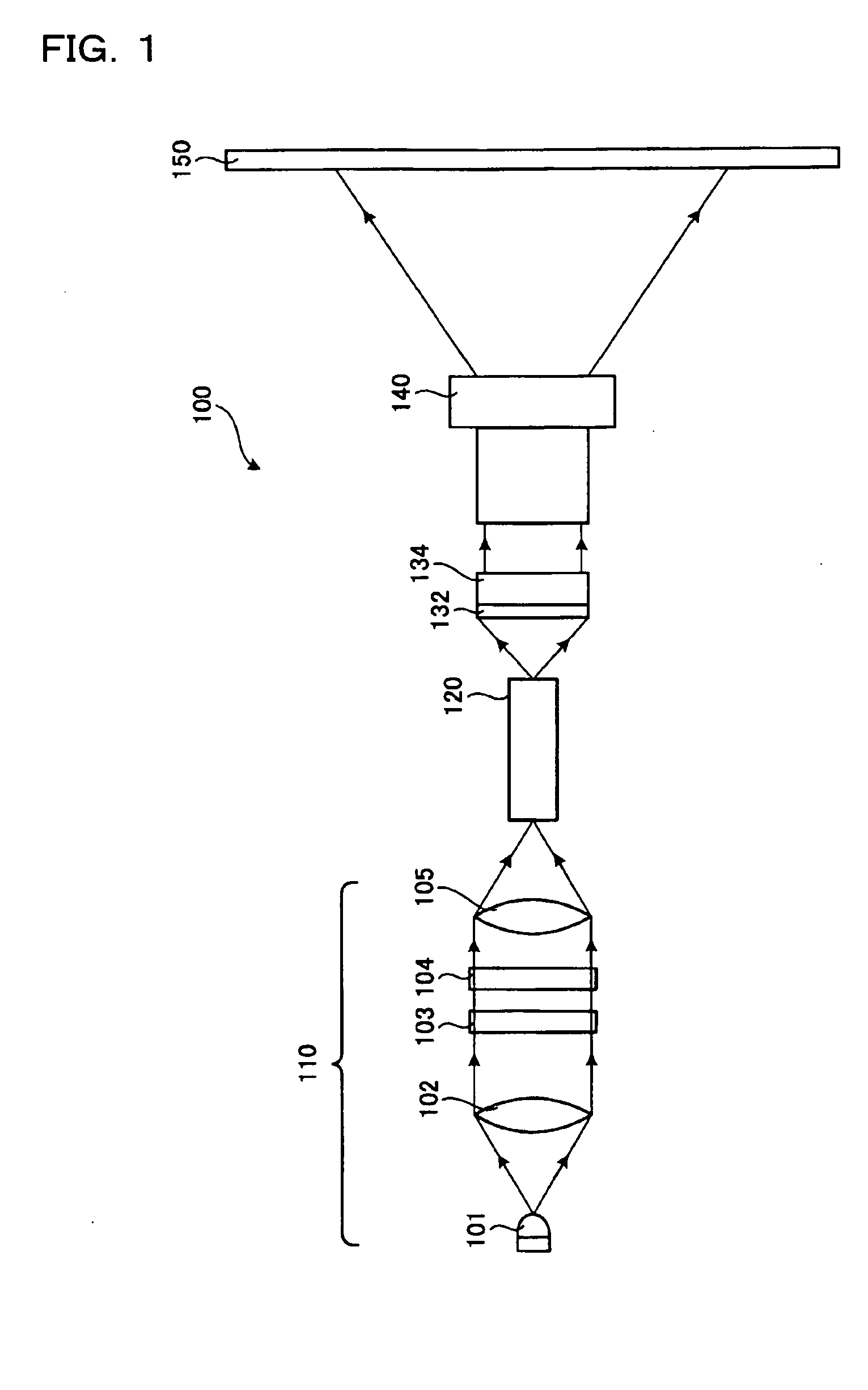
[0009] In the incoming light to the reflecting type polarizing plate, polarized light in a particular oscillation direction can be transmitted through the reflecting type polarizing plate. Meanwhile, light in another oscillation direction other than the particular oscillation direction is reflected by the reflecting type polarizing plate and returns toward the light source. When the reflecting portion is provided at the light source, for example, light returning from the reflecting type polarizing plate to the light source can be reflected by the reflecting portion and again advances toward the reflecting type polarizing plate. The collimating optical system provided between the light source and the reflecting type polarizing plate causes the light reflected by the reflecting type polarizing plate to advance in the substantially same path in which the light has advanced toward the reflecting type polarizing plate. Therefore, the light reflected by the reflecting type polarizing plate can efficiently be returned to the light source. In this way, in the process in which polarized light recycles in the
optical path between the reflecting portion and the reflecting type polarizing plate, polarized light in a particular oscillation direction can sequentially be extracted by the reflecting type polarizing plate. Consequently, polarized light in the particular oscillation direction can be obtained with high use efficiency.
[0010] Since the light from the light source is collimated into a substantially
parallel beam by the collimating optical system, light from the light source is entered in a direction substantially orthogonal to the reflecting type polarizing plate. Since the light from the light source is entered in a direction substantially orthogonal to the reflecting type polarizing plate, the light from the light source can be efficiently separated. Furthermore, since the reflecting type polarizing plate is provided outside the light source, it can be prevented from being deteriorated by heat from the light source and the light source can readily be produced. The illuminating device according to the invention can supply polarized light in a particular oscillation direction without doubling the beam from the light source. Therefore, the beam from the light source can effectively be used in the optical system in the projector. The effective use of the beam from the light source allows the device to readily adapt to the arrangement of a plurality of light sources in an array. In this way, polarized light in a particular oscillation direction can sufficiently be supplied and an illuminating device suitable for a projector having a liquid
crystal type spatial light modulator can be provided.
[0012] Preferably, according to exemplary embodiments of the invention, a plurality of light sources in an array can be provided, and a plurality of collimating optical systems and a plurality of reflecting type polarizing plates are provided in an array corresponding to the light sources. As in the foregoing, the illuminating device according to the invention can readily be adapted to a plurality of light sources arranged in an array. Since the collimating optical systems and the reflecting type polarizing plates are provided corresponding to the light sources, an illuminating device capable of efficiently supplying light from the plurality of light sources is provided.
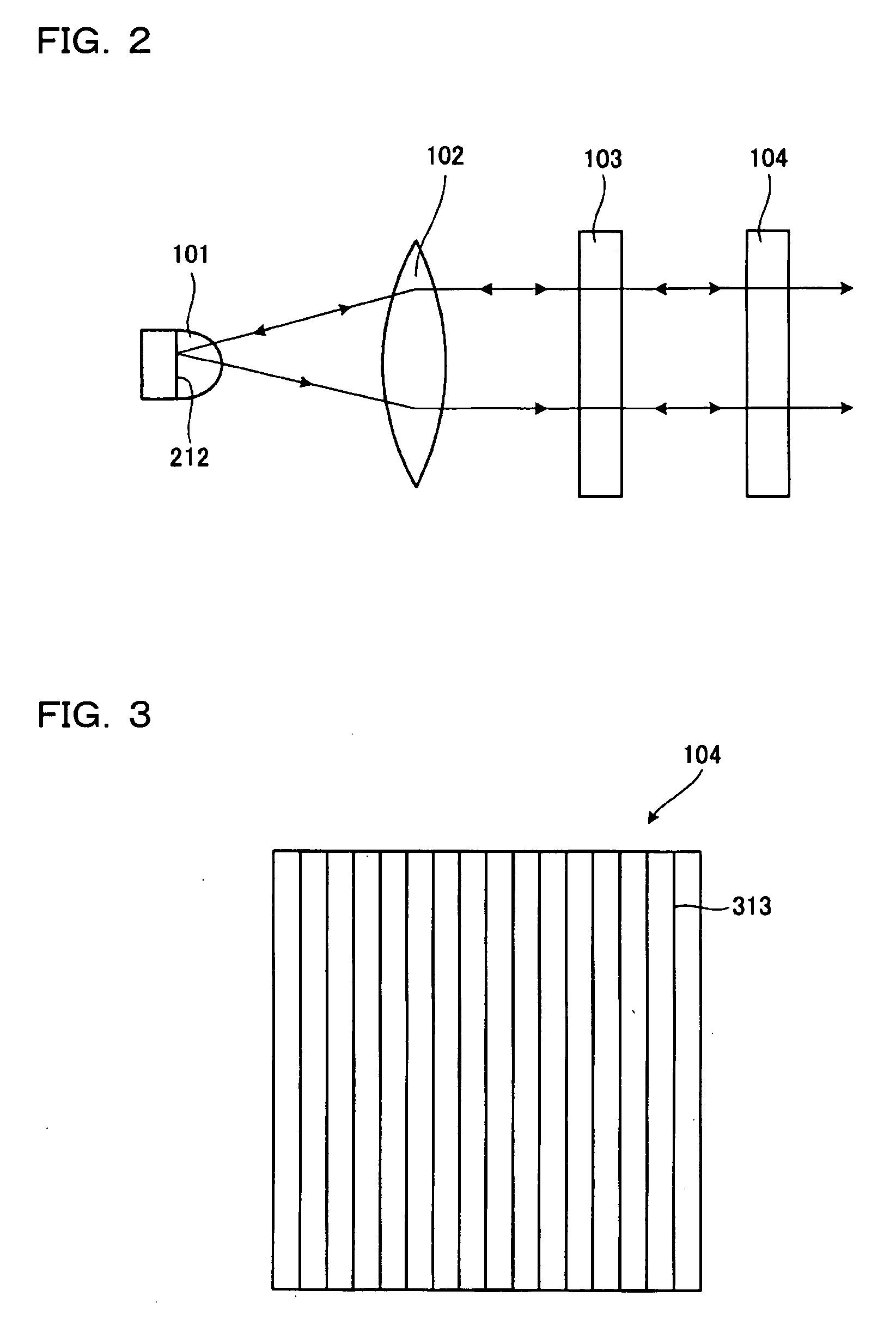
[0013] According to the exemplary embodiment, a
phase plate can be desirably provided between the collimating optical system and the reflecting type polarizing plate. The
phase plate converts, for example,
linearly polarized light reflected by the reflecting type polarizing plate into circularly polarized light. The circularly polarized light advancing toward the light source is reflected by the reflecting portion provided at the light source and then transmitted through the
phase plate again, so that the light is converted into
linearly polarized light. For example, the use of the λ / 4 phase plate allows
linearly polarized light reflected by the reflecting type polarizing plate to be transmitted through the phase plate twice, so that the phase changes by λ / 2. Therefore, part of the linearly polarized light reflected by the reflecting type polarizing plate can be converted into linearly polarized light in a particular oscillation direction before the light comes into the reflecting type polarizing plate again. The light converted into linearly polarized light in the particular oscillation direction can be transmitted through the reflecting type polarizing plate. Meanwhile, the linearly polarized light converted into light in another oscillation direction different from the particular oscillation direction by being transmitted through the phase plate again is reflected by the reflecting type polarizing plate and the above described recycling process is repeated. In this way, the use of the phase plate allows a desired linearly polarized optical component to be extracted even more efficiently. According to aspects of the invention, light can be entered in a direction substantially orthogonal to the phase plate. Since the light can be entered in a direction substantially orthogonal to the phase plate, the conversion between the linearly polarized light and the circularly polarized light can efficiently be carried out.
[0014] According to the exemplary embodiment, there is preferably provided a lens system that gathers polarized light transmitted through the reflecting type polarizing plate. The use of the lens system for gathering the polarized light allows the polarized light to efficiently advance to a particular region. In this way, the lens system advances the polarized light into the particular region, so that the light can efficiently be advanced to the particular region even when a plurality of light sources are provided in an array.
[0015] Furthermore, a projector according to the invention can include an illuminating device that supplies polarized light in a particular oscillation direction, a light guiding optical system that substantially equalizes the intensity distribution of the polarized light from the illuminating device, a spatial light modulator responsive to an
image signal for modulating light from the light guiding optical system, and a projecting lens that projects the light from the spatial light modulator. The illuminating device can be the above-described illuminating device. Since the projector according to the invention can use the illuminating device described above, images with higher brightness can be obtained with high light use efficiency. Even when a plurality of light sources are arranged in an array, the light guiding optical system does not have to be large or a plurality of openings are not necessary at the end
plane of incidence of the light guiding optical system. Therefore, the projector can be simple and compact.

