Imaging lens

a technology of imaging lens and lens body, which is applied in the field of imaging lens, can solve the problems of insufficient compactness of lens system, inability to design a sufficiently compact lens system, and inability to enlarge the optical length of the lens, so as to achieve satisfactory image, short lens optical length, and satisfactory brightness.

Active Publication Date: 2005-07-21
SEIKOH GIKEN
View PDF6 Cites 12 Cited by
  • Summary
  • Abstract
  • Description
  • Claims
  • Application Information

AI Technical Summary

Benefits of technology

[0041] If on the other hand the F-number is smaller than the upper limit given by the condition equation (5), then an image with satisfactory brightness can be obtained, without excessively dark images, and without insufficient light quantity arriving at the image plane of the portable telephone, image input device for a personal computer, digital camera, surveillance CCD camera, inspection equipment, or similar.
[0042] As explained above, by adopting a lens configuration satisfying the five conditions of the above condition equations (1) through (5), an imaging lens can be provided with an F-number in the range from 2.0 to 4.0, configured from only two lenses, with a short lens optical length, and from which satisfactory images are obtained. In addition, by providing a diaphragm between the first lens and second lens to sufficiently eliminate flare, an imaging lens can be provided with sufficiently enhanced image contrast and from which sharp images are obtained.
[0043] By means of an imaging lens of the present invention, it is possible to form all of the lenses (two lenses) making up the imaging lens of the present invention from plastic material, so that imaging lenses can be provided at low cost and which are light in weight.

Problems solved by technology

However, such an infrared lens has a broad interval D between the first lens and second lens, so that as a result the optical length is necessarily long, and design of a sufficiently compact lens system is difficult.
However, this image-forming lens system has a short back focus, so that insertion of a filter or similar between lenses and image plane to block infrared light is difficult.
However, these imaging lenses have a configuration in which the thickness of the image-forming lens on the optical axis is large.
Consequently the refractive index tends to be distributed unevenly when configuring the lens, and image distortion and similar occur due to such uneven distribution of the refractive index, so that in some cases the image quality which should result from lens design cannot be obtained.
Consequently flare cannot be eliminated adequately, and consequently there are limits to the ability to raise the contrast of the image and obtain sharp images.
That is, in this design the optical length is long, and compactness cannot be completely attained.
Consequently in this configuration, a diaphragm could not easily be inserted as a second diaphragm between the first and second lenses.

Method used


Image

  • Imaging lens
  • Imaging lens
  • Imaging lens

Examples


embodiment 1

[0082] (A) The focal length f1 of the first lens L1 is 1.63 mm.

[0083] (B) The focal length f2 of the second lens L2 is 1.74 mm.

[0084] (C) The combined focal length f for all lenses is 1.0 mm.

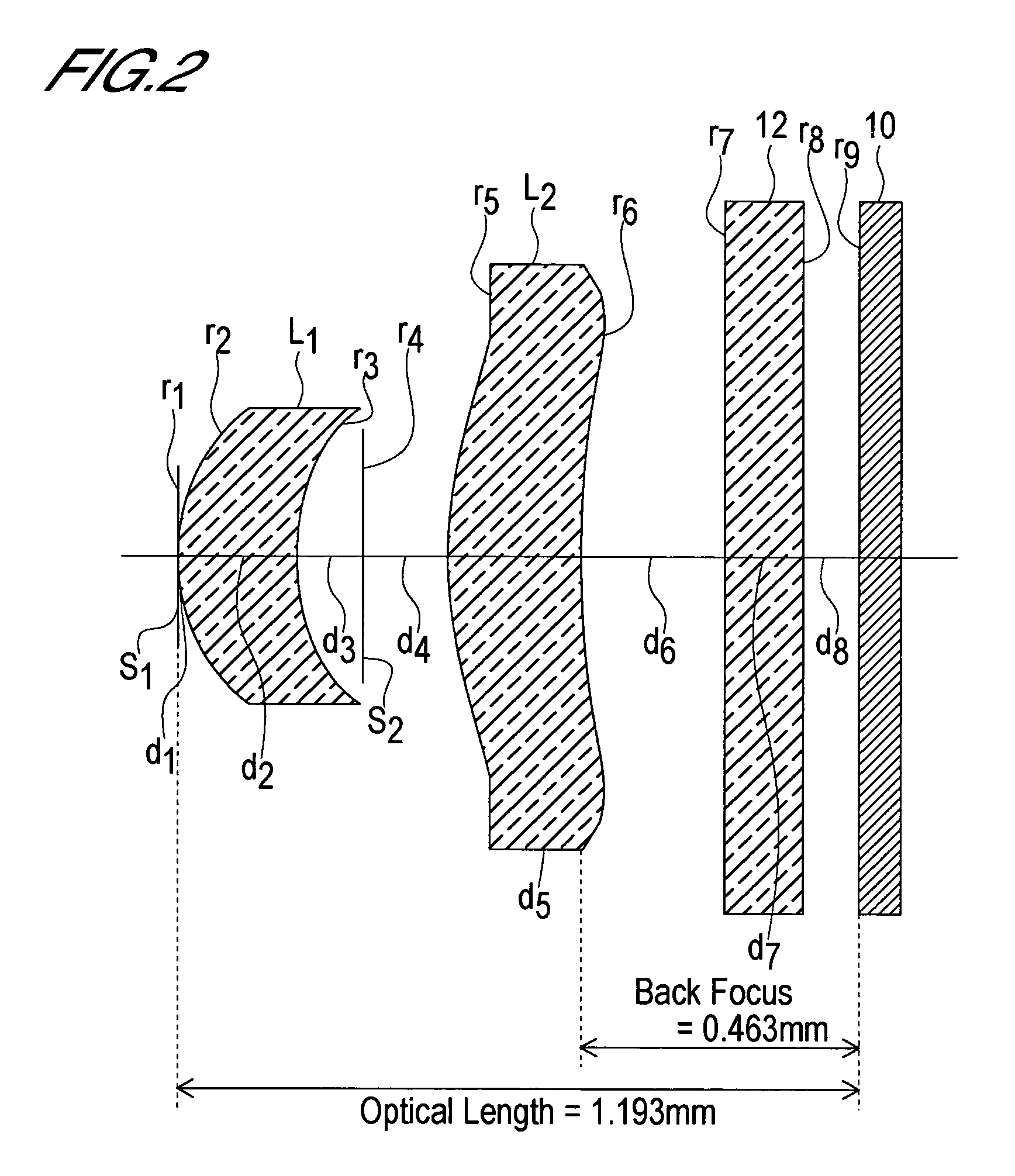
[0085] (D) The back focus bf is 0.463 mm.

[0086] (E) The optical length d is 1.193 mm.

[0087] (F) The interval D2 between the first lens L1 and the second lens L2 is 0.2738 mm.

[0088] (G) The F-number Fno is 3.0.

[0089] Hence:

f1 / f2=1.63 / 1.74=0.9368

bf / f=0.463 / 1.0=0.463

d / f=1.193 / 1.0=1.193

D2 / f=0.2738 / 1.0=0.2738

Fno=3.0

[0090] Therefore the lens system of Embodiment 1 satisfies all of the following condition equations (1) through (5).

0.3<f1 / f2<1.0   (1)

0.4<bf / f<0.5   (2)

1.0<d / f<1.3   (3)

0.12<D2 / f<0.30   (4)

2.0no<4.0   (5)

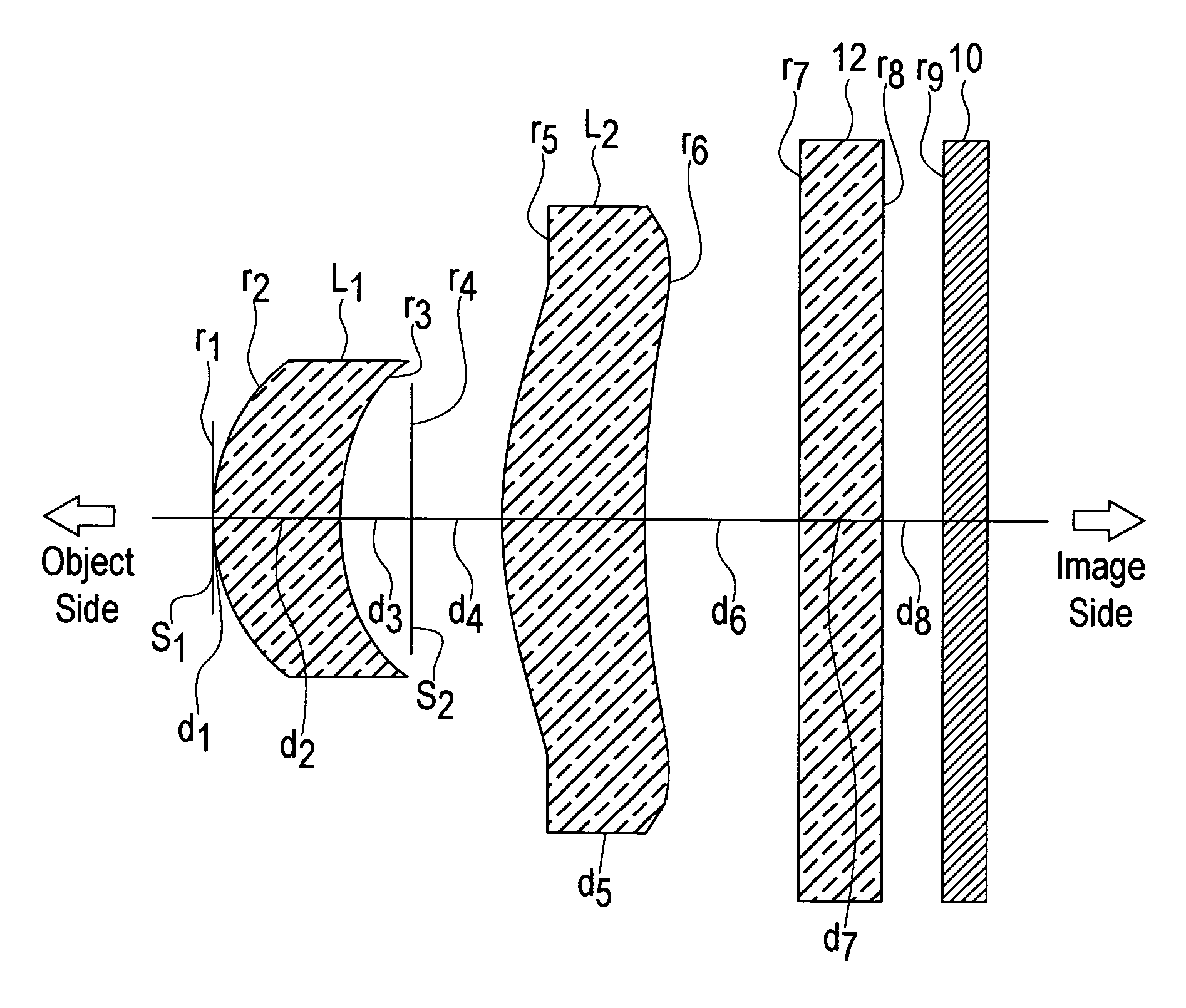
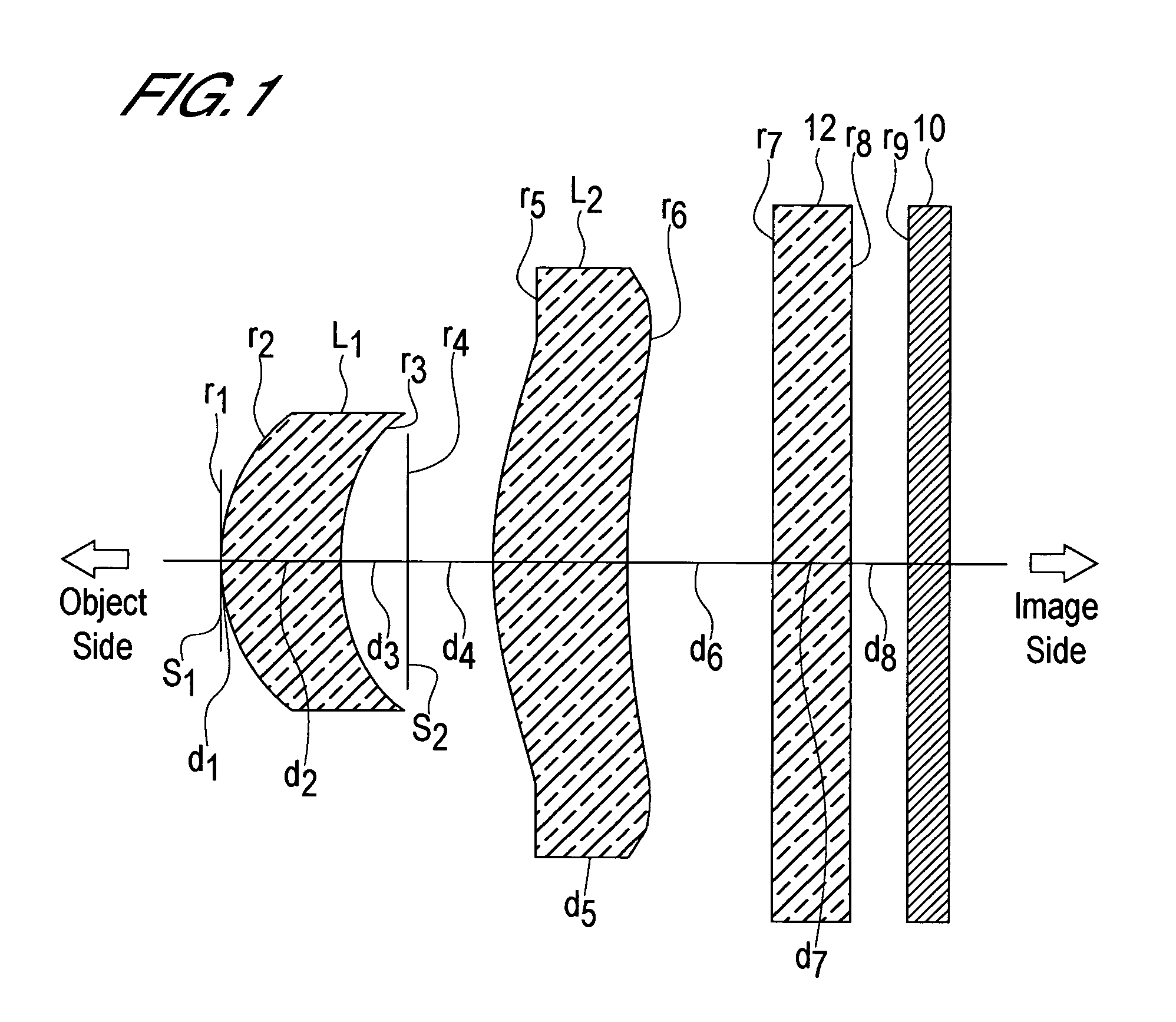
[0091] As indicated in Table 1, the aperture diaphragm S1 is provided at the position of the first surface r2 (the object-side surface) of the first lens L1. The second diaphragm S2 is provided at the position 0.1217 mm (d3=0.1217 mm) behind the sec...

embodiment 2

[0098] (A) The focal length f1 of the first lens L1 is 1.36 mm.

[0099] (B) The focal length f2 of the second lens L2 is 2.48 mm.

[0100] (C) The combined focal length f for all lenses is 1.0 mm.

[0101] (D) The back focus bf is 0.454 mm.

[0102] (E) The optical length d is 1.102 mm.

[0103] (F) The interval D2 between the first lens L1 and the second lens L2 is 0.1727 mm.

[0104] (G) The F-number Fno is 3.0.

[0105] Hence:

f1 / f21.36 / 2.48=0.5484

bf / f=0.454 / 1.0=0.454

d / f=1.102 / 1.0=1.102

D2 / f=0.1727 / 1.0=0.1727

Fno=3.0

[0106] Therefore the lens system of Embodiment 2 satisfies all of the following condition equations (1) through (5).

0.3<f1 / f2<1.0   (1)

0.4<bf / f<0.5   (2)

1.0<d / f<1.3   (3)

0.12<D2 / f<0.30   (4)

2.0no<4.0   (5)

[0107] As indicated in Table 2, the aperture diaphragm S1 is provided at the position of the first surface r2 (the object-side surface) of the first lens L1. The second diaphragm S2 is provided at the position 0.1007 mm (d3=0.1007 mm) behind the seco...

embodiment 3

[0114] (A) The focal length f1 of the first lens L1 is 1.29 mm.

[0115] (B) The focal length f2 of the second lens L2 is 2.89 mm.

[0116] (C) The combined focal length f for all lenses is 1.0 mm.

[0117] (D) The back focus bf is 0.462 mm.

[0118] (E) The optical length d is 1.079 mm.

[0119] (F) The interval D2 between the first lens L1 and the second lens L2 is 0.1435 mm.

[0120] (G) The F-number Fno is 3.0.

[0121] Hence:

f1 / f2=1.29 / 2.89 0.4464

bf / f=0.462 / 1.0=0.462

d / f=1.079 / 1.0=1.079

D2 / f=0.1435 / 1.0=0.1435

Fno=3.0

[0122] Therefore the lens system of Embodiment 3 satisfies all of the following condition equations (1) through (5).

0.3<f1 / f2<1.0   (1)

0.4<bf / f<0.5   (2)

1.0<d / f<1.3   (3)

0.12<D2 / f<0.30   (4)

2.0no<4.0   (5)

[0123] As indicated in Table 3, the aperture diaphragm S1 is provided at the position of the first surface r2 (the object-side surface) of the first lens L1. The second diaphragm S2 is provided at the position 0.0861 mm (d3=0.0861 mm) behind the sec...


PUM


Abstract

The present invention relates to an imaging lens with an F-number in the range 2.0 to 4.0, configured from only two lenses, with a short lens optical length, and with sufficiently high image contrast so that sharp images are obtained. The imaging lens is configured by positioning, in order from an object side to an image side, an aperture diaphragm, a first lens, a second diaphragm, and a second lens, satisfying the following conditions. The first lens and second lens are both meniscus-shaped with convex surface facing the object side, and have positive refractive power.
0.3<f1/f2<1.0   (1)
0.4<bf/f<0.5   (2)
1.0<d/f<1.3   (3)
0.12<D2/f<0.30   (4)
2.0<Fno<4.0   (5)
Here f is the combined focal length of the imaging lens, f1 is the focal length of the first lens, f2 is the focal length of the second lens, bf is the distance (in air) from the image-side surface of the second lens to the image plane, d is the distance (in air) from the object-side surface of the first lens to the image plane, D2 is the interval between the first lens and the second lens, and Fno is the F-number.

Description

BACKGROUND OF THE INVENTION [0001] 1. Field of the Invention [0002] The present invention relates to an imaging lens, and in particular to an imaging lens suitable for mounting in a portable telephone, image input device for a personal computer, digital camera, surveillance CCD camera, inspection device, or similar equipment, which uses a CCD or CMOS device as an imaging component. [0003] 2. Description of Related Art [0004] In the above-described imaging lens, it is necessary that the optical length, defined as the distance from the incidence plane on the object side of the imaging lens to the image plane (image-forming surface of the CCD or similar), be short. That is, in the design of the imaging lens, measures must be taken to reduce insofar as possible the ratio of the optical length to the combined focal length of the imaging lens. Hereafter, an imaging lens with a short optical length, that is, the ratio of the optical length to the focal length of which is small, may be call...

Claims


Application Information

Patent Timeline
Patent Type & Authority Applications(United States)
IPC IPC(8): G02B9/04G02B9/06G02B13/00G02B13/18
CPCG02B13/003G02B9/06G02B1/041G02B13/18G02B9/08G03B9/02
Inventor DO, SATOSHIHASHIMOTO, YOSHIYUKI
Owner SEIKOH GIKEN
Why Eureka
Try Eureka