Method and device for controlling pump torque for hydraulic construction machine

a technology of hydraulic construction machine and pump torque, which is applied in the direction of positive displacement liquid engine, fluid coupling, servomotor, etc., can solve the problems of engine stalling, noise generation, and affecting the operation of operators, so as to reduce prevent engine stalling , the effect of reducing the maximum absorption torque of the hydraulic pump

Inactive Publication Date: 2005-07-28
NIHON KENKI CO LTD
View PDF5 Cites 25 Cited by
  • Summary
  • Abstract
  • Description
  • Claims
  • Application Information

AI Technical Summary

Benefits of technology

[0009] With the speed sensing control disclosed in JP,A 11-101183, JP,A 2000-73812, JP,A 2000-73960, etc., the pump base torque is modified in response to a lowering of the engine output caused by changes of the environment factors detected by the sensors, such as the atmospheric pressure, the fuel temperature and the cooling water temperature, so that the lowering of the engine revolution speed caused by the speed sensing control can be prevented. However, because those known techniques employ the sensors provided in prediction of various environment factors in advance and utilize values detected by the sensors, they are not adaptable for a lowering of the engine output attributable to environment factors which cannot be predicted in advance. Also, those known techniques are not adaptable for a lowering of the engine output attributable to other factors, e.g., the use of poor fuel, which are difficult to detect by sensors. Further, many sensors are required to detect the various environment factors, and maps in the same number as the sensors must be prepared and installed in a controller, thus resulting in an increased cost.
[0030] With those features, the maximum absorption torque of the hydraulic pump can be controlled by combination of both the control according to the present invention and the known speed sensing control. Therefore, a control response can be improved even when an abrupt load is applied.

Problems solved by technology

However, the above-described prior art has problems as follows.
Accordingly, whenever such a shift occurs during work in which the load condition changes to the high-load condition. e.g., work of excavating earth and sand, the engine revolution speed lowers, thus generating noise and making an operator feel unpleasant or fatigue.
However, because those known techniques employ the sensors provided in prediction of various environment factors in advance and utilize values detected by the sensors, they are not adaptable for a lowering of the engine output attributable to environment factors which cannot be predicted in advance.
Also, those known techniques are not adaptable for a lowering of the engine output attributable to other factors, e.g., the use of poor fuel, which are difficult to detect by sensors.
Further, many sensors are required to detect the various environment factors, and maps in the same number as the sensors must be prepared and installed in a controller, thus resulting in an increased cost.

Method used


Image

  • Method and device for controlling pump torque for hydraulic construction machine
  • Method and device for controlling pump torque for hydraulic construction machine
  • Method and device for controlling pump torque for hydraulic construction machine

Examples


first embodiment

[0044] the present invention will be first described with reference to FIGS. 1 to 8.

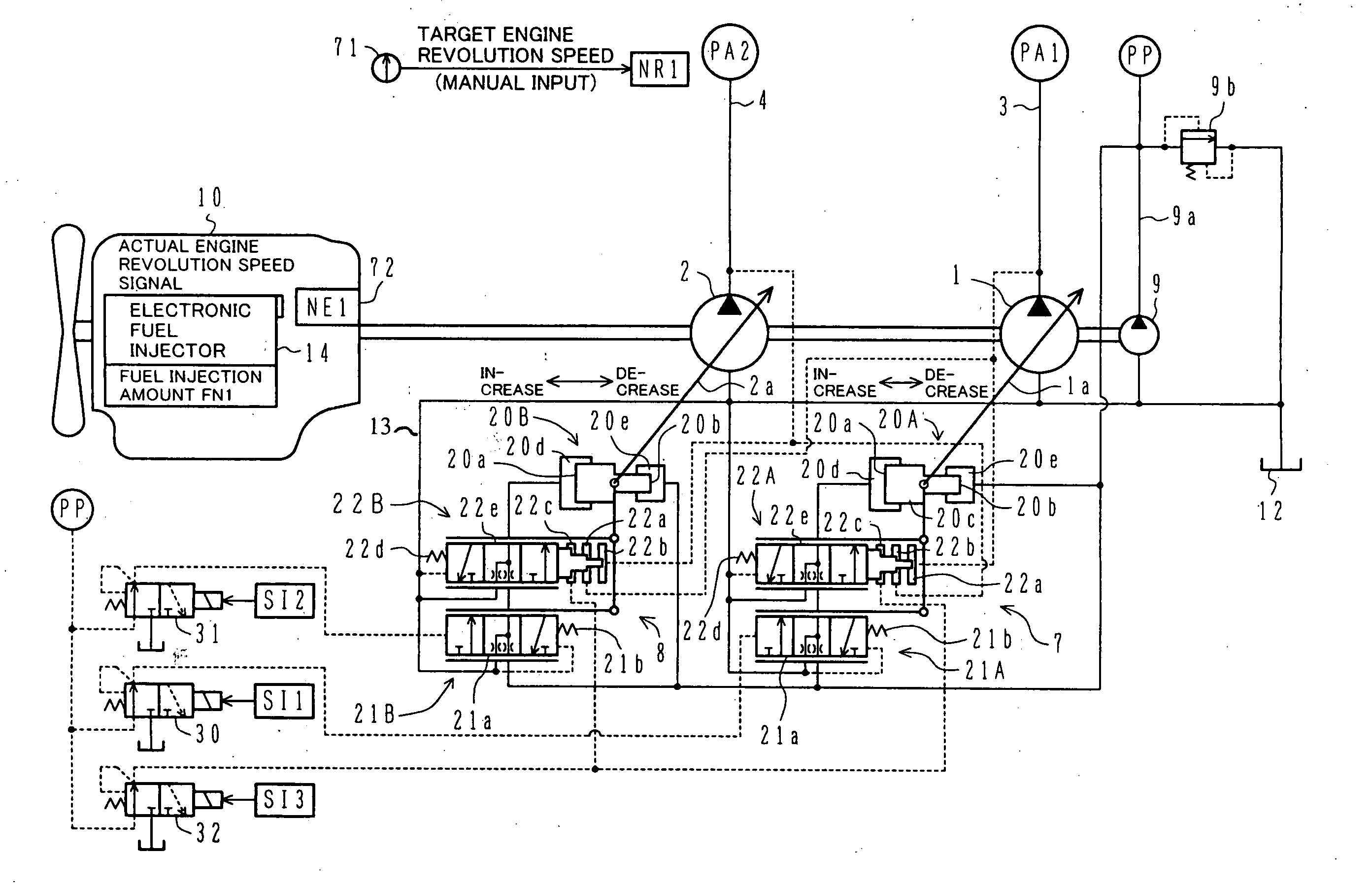
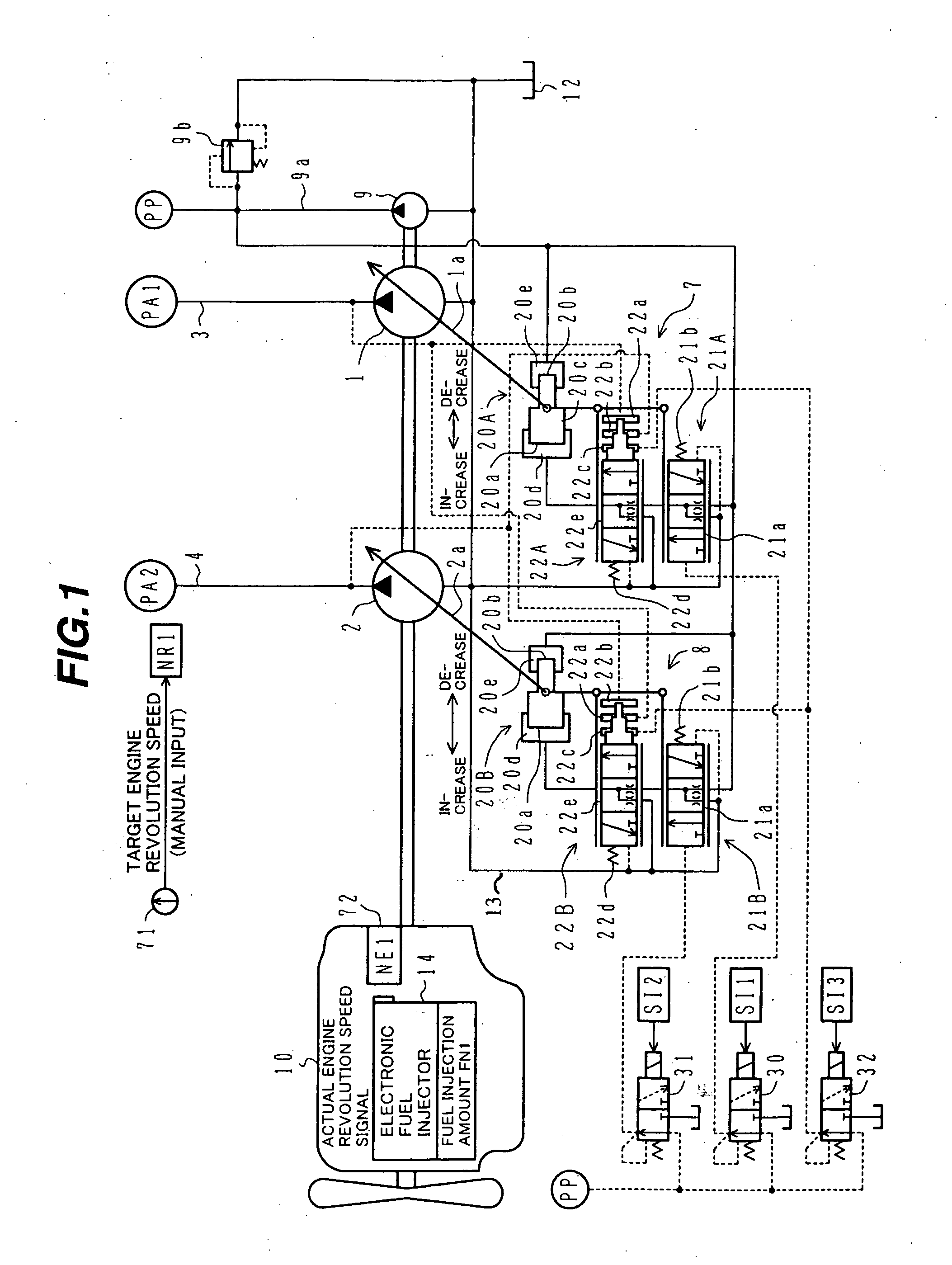
[0045] In FIG. 1, reference numerals 1 and 2 denote variable displacement hydraulic pumps of, e.g., swash plate type. Numeral 9 denotes a fixed displacement pilot pump. The hydraulic pumps 1, 2 and the pilot pump 9 are connected to an output shaft 11 of a prime mover 10 and are driven by the prime mover 10 for rotation.

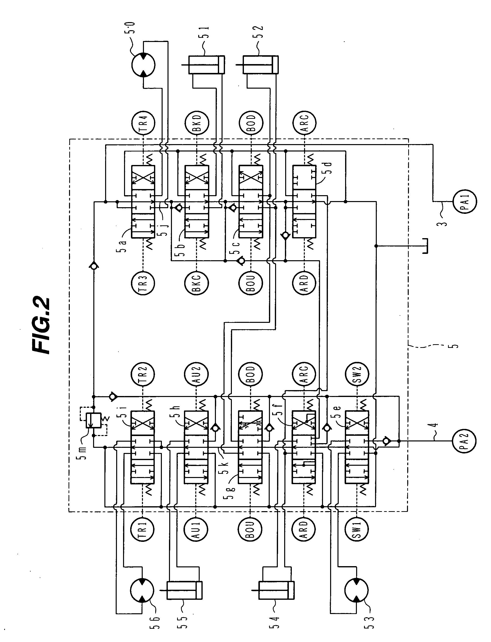
[0046] A valve unit 5, shown in FIG. 2, is connected to delivery lines 3, 4 of the hydraulic pumps 1, 2. A hydraulic fluid is supplied to a plurality of actuators 50 to 56 through the valve unit 5, thereby driving the actuators. A pilot relief valve 9b for holding the delivery pressure of the pilot pump 9 at a certain pressure is connected to a delivery line 9a of the pilot pump 9.

[0047] Details of the valve unit 5 will be described below.

[0048] In FIG. 2, the valve unit 5 has two valve groups comprising respectively flow control valves 5a-5d and flow control valves 5e-5i. The flow ...


PUM


Abstract

A current load rate of an engine 10 is computed and a maximum absorption torque of at least one hydraulic pump 1, 2 is controlled so that the load rate is held at a target value. Engine stalling can be prevented by decreasing the maximum absorption torque of the hydraulic pump under a high-load condition. When an engine output lowers due to environmental changes, the use of poor fuel or other reasons, the maximum absorption torque of the hydraulic pump can be decreased without a lowering of the engine revolution speed. Further, the present invention is adaptable for any kinds of factors causing a lowering of the engine output, such as those factors that cannot be predicted in advance or are difficult to detect by sensors. In addition, because of no necessity of sensors, such as environment sensors, the manufacturing cost can be reduced.

Description

TECHNICAL FIELD [0001] The present invention relates to a pump torque control method and system for a hydraulic construction machine in which a diesel engine is installed as a prime mover and a variable displacement hydraulic pump is driven by the engine to drive an actuator. BACKGROUND ART [0002] Generally, in a hydraulic construction machine such as a hydraulic excavator, a diesel engine is installed as a prime mover and a variable displacement hydraulic pump is driven by the engine to drive an actuator, thereby carrying out predetermined work. Engine control in that type of hydraulic construction machine is generally performed by setting a target fuel injection amount and controlling a fuel injector in accordance with the target fuel injection amount. [0003] Also, control of the hydraulic pump is generally performed as displacement control in accordance with a demanded flow rate and as torque control (horsepower control) in accordance with a pump delivery pressure. In the torque ...

Claims


Application Information

Patent Timeline
Patent Type & Authority Applications(United States)
IPC IPC(8): E02F9/22F02D1/08F02D29/00F02D29/04F04B17/05F04B23/06F04B49/00F04B49/06F04B49/08F15B11/16F15B21/08
CPCE02F9/2235E02F9/226E02F9/2292E02F9/2296F04B49/08F04B23/06F04B49/002F04B49/065F04B17/05F04B49/06
Inventor NAKAMURA, KAZUNORIKOWATARI, YOICHIISHIKAWA, KOUIJIARAI, YASUSHI
Owner NIHON KENKI CO LTD
Why Eureka
Try Eureka