Sensor element, in particular a planar gas sensor element

a sensor element and gas sensor technology, applied in the field of sensor elements, can solve the problems of mechanical stresses which occur in the sensor element during operation and/or manufacture, and achieve the effects of improving heat transfer, preventing unwanted heat dissipation, and poor thermal conductivity

Inactive Publication Date: 2005-07-28
ROBERT BOSCH GMBH
View PDF9 Cites 12 Cited by
  • Summary
  • Abstract
  • Description
  • Claims
  • Application Information

AI Technical Summary

Benefits of technology

[0015] It is also advantageous that improved heat transfer from the heater structure into the sensor structure is achievable in that the rear area of the sensor element in the area of the inlays. The side of the sensor element laterally opposite the heater lead wire is surrounded by the spacer layers designed as a frame. The zirconium dioxide, which has poor thermal conductivity, provided in this rear area thus prevents unwanted heat dissipation. Moreover, this rear area may now have a lateral extension, as defined by the width of the frame, of significantly greater than 300 μm, e.g., 500 μm to 2000 μm, thereby also contributing to the reduction in heat dissipation.
[0016] To further improve the heat transfer from the heater structure in the direction of the sensor structure, it is advantageous when the second inlay on the side of the heater structure facing away from the sensor structure has a porosity or a porous void structure created in particular with the help of a pore forming agent in the course of a sintering operation used in the manufacture of the sensor element. Alternatively or additionally, the second inlay may also be provided with cubical, cylindrical, or lenticular milled-out areas or recesses.
[0017] It is also frequently advantageous when the electrically insulating first inlay used on the side of the heater structure facing the sensor structure has a porosity or porous void structure created using a pore forming agent and/or when the first inlay has cubical, cylindrical or lenticular recesses, for example. Due to this structure of the first inlay, the heat transfer from the heater structure in the direction of the sensor structure is initially somewhat hindered, but this advantageously further reduces the capacitive input of electric signals from the heater structure into the sensor structure. Moreover, a poros

Problems solved by technology

One disadvantage of these two methods, however, is the mechanical stresses which occur in the sensor element during operation and/or manufacture and are caused mainly by differenc

Method used


Image

  • Sensor element, in particular a planar gas sensor element
  • Sensor element, in particular a planar gas sensor element
  • Sensor element, in particular a planar gas sensor element

Examples


Embodiment Construction

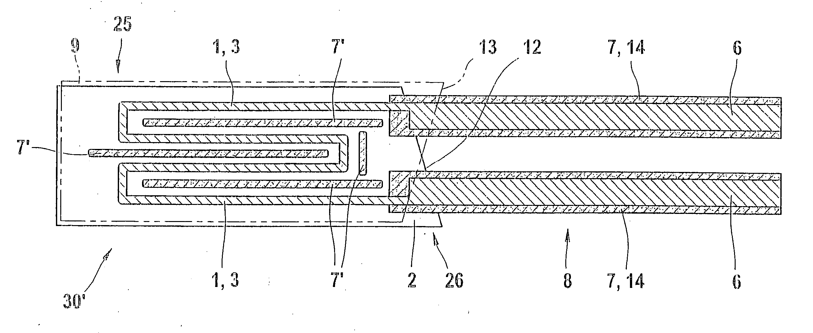
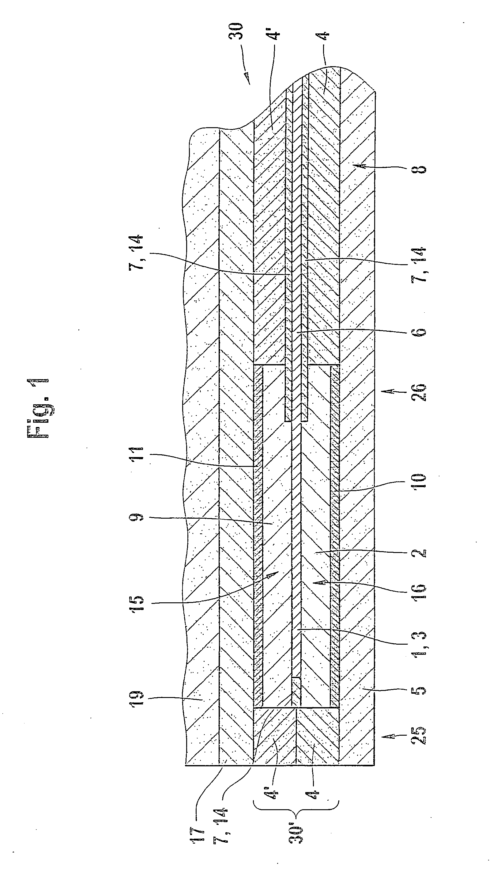
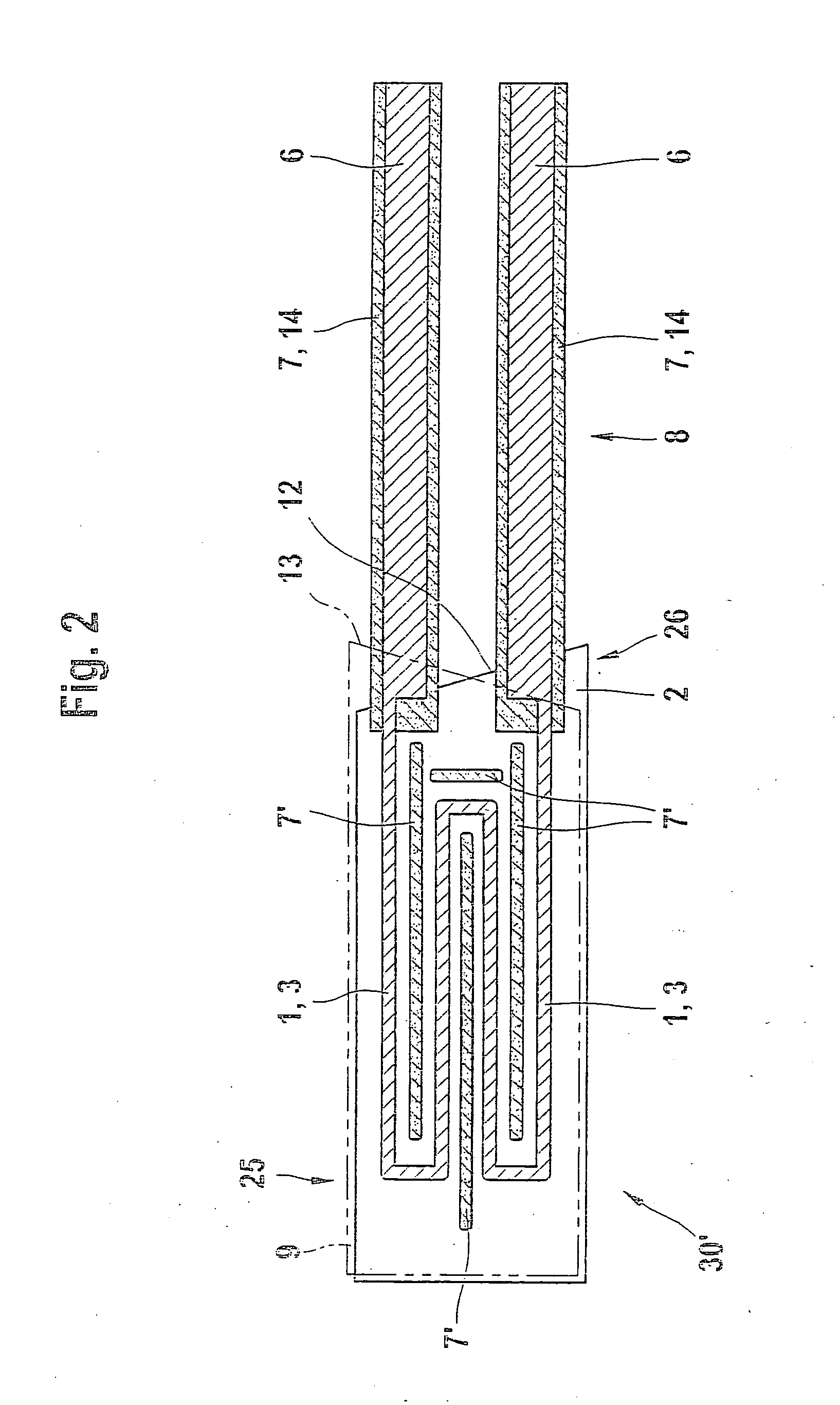
[0027]FIG. 1 shows a sensor element 30 having a sensor structure 19 and a heater area 30′. With regard to the production of sensor element 30 according to FIG. 1, known techniques are used, i.e., ceramic green films onto which other layers are printed as needed, then stacked, laminated and finally sintered to form sensor element 30.

[0028]FIG. 1 shows in detail a sintered ceramic sensor element 30 in the form of a planar gas sensor element having a solid electrolyte including a bottom layer or a substrate 5 of zirconium dioxide on which there is a second intermediate layer 10 in some areas, printed onto the ceramic green film that forms substrate 5 at the time of its manufacture. A second spacer layer 4 of zirconium dioxide is also provided and forms a lower frame, thus defining a trough-shaped second recess 16 into which a second inlay 2 is placed after the printing of second intermediate layer 10 and deposition of second spacer layer 4 onto substrate 5. In the example described he...


PUM


Abstract

A sensor element, in particular a planar gas sensor element, having a sensor structure is described, which is heatable by a heater structure. A first spacer layer is provided between the heater structure and the sensor structure, the spacer layer having a first recess in the area of the heater structure into which a first inlay, which electrically insulates the heater structure from the sensor structure, is inserted.

Description

FIELD OF THE INVENTION [0001] The present invention relates to a sensor element, in particular a planar gas sensor element, such as a lambda probe or a nitrogen oxide sensor, that includes a solid electrolyte and a heater structure. BACKGROUND INFORMATION [0002] Planar gas sensor elements (“lambda probes”), may be heated using a heating device having a heater structure that is incorporated into a multilayer ceramic layer structure. A main function of the heating is to stabilize the sensor element signal. German Published Patent Application No. 199 06 908 (the '908 application) describes a heater structure designed as a platinum resistance conductor in a meandering pattern between two ceramic layers in the hot area of the gas sensor element, i.e., in the area in which the measuring and reference electrodes are situated, and which is exposed to the gas to be analyzed. [0003] In the case of ceramic gas sensor elements based on a solid electrolyte made substantially of zirconium dioxide...

Claims


Application Information

Patent Timeline
IPC IPC(8): G01N27/406G01N27/409G01N27/41H05B3/28
CPCG01N27/4067H05B2203/022H05B3/283
Inventor SCHUMANN, BERNDEISELE, ULRICH
Owner ROBERT BOSCH GMBH
Why Eureka
Try Eureka