Method of cutting material with hybrid liquid-jet/laser system

a liquid-jet and laser system technology, applied in laser beam welding apparatus, metal working apparatus, manufacturing tools, etc., can solve the problems of melt dross formation on the inside edge of cut tubes or sheets, and the procedures which produce satisfactory end products when using conventional laser systems are not generally applicable, so as to reduce the lead-in path length

Inactive Publication Date: 2005-07-28
BOSTON SCI SCIMED INC
View PDF71 Cites 27 Cited by
  • Summary
  • Abstract
  • Description
  • Claims
  • Application Information

AI Technical Summary

Benefits of technology

[0015] In another embodiment, the present invention comprises a method of providing one or more shaped openings through the wall of a tube of material comprising of a tube of material having a thickness and a cutting device to provide a hybrid liquid-jet/laser stream. A cut lead-in may be established by mov

Problems solved by technology

The conventional laser cutting process typically results in the formation of melt dross on the inside edge of the cut tube or sheet.
Procedures which

Method used


Image

  • Method of cutting material with hybrid liquid-jet/laser system
  • Method of cutting material with hybrid liquid-jet/laser system
  • Method of cutting material with hybrid liquid-jet/laser system

Examples


Embodiment Construction

[0023] While this invention may be embodied in many different forms, there are described in detail herein specific embodiments. This description is an exemplification of the principles of the invention and is not intended to limit the invention to the particular embodiments illustrated.

[0024] For the purposes of this disclosure, like reference numerals in the figures shall refer to like features unless otherwise indicated.

[0025] U.S. patent application Ser. No. 10 / 190,975 disclosing a vertical stent cutting process, and U.S. patent application Ser. No. 10 / 190,424 disclosing a tubular cutting process and system, are incorporated herein by reference.

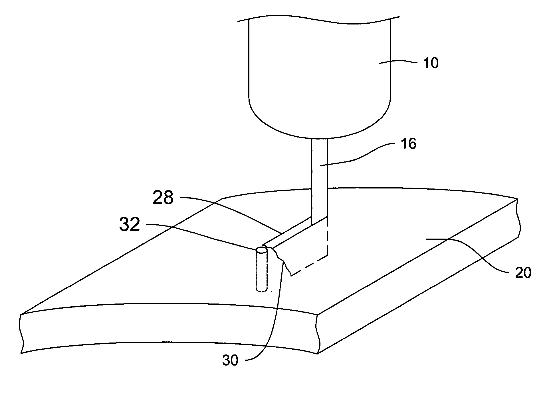
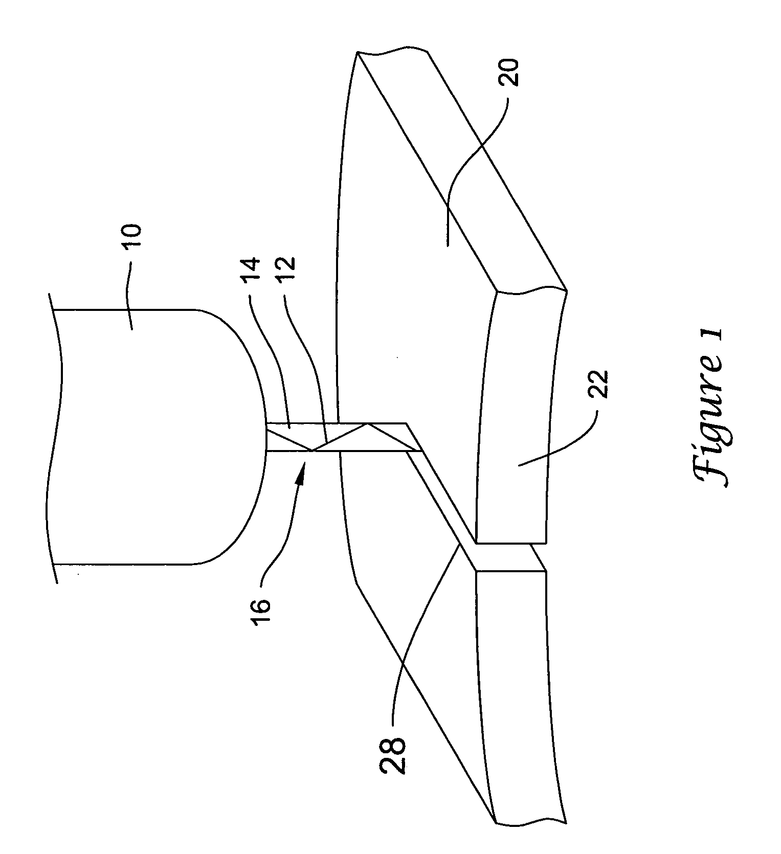
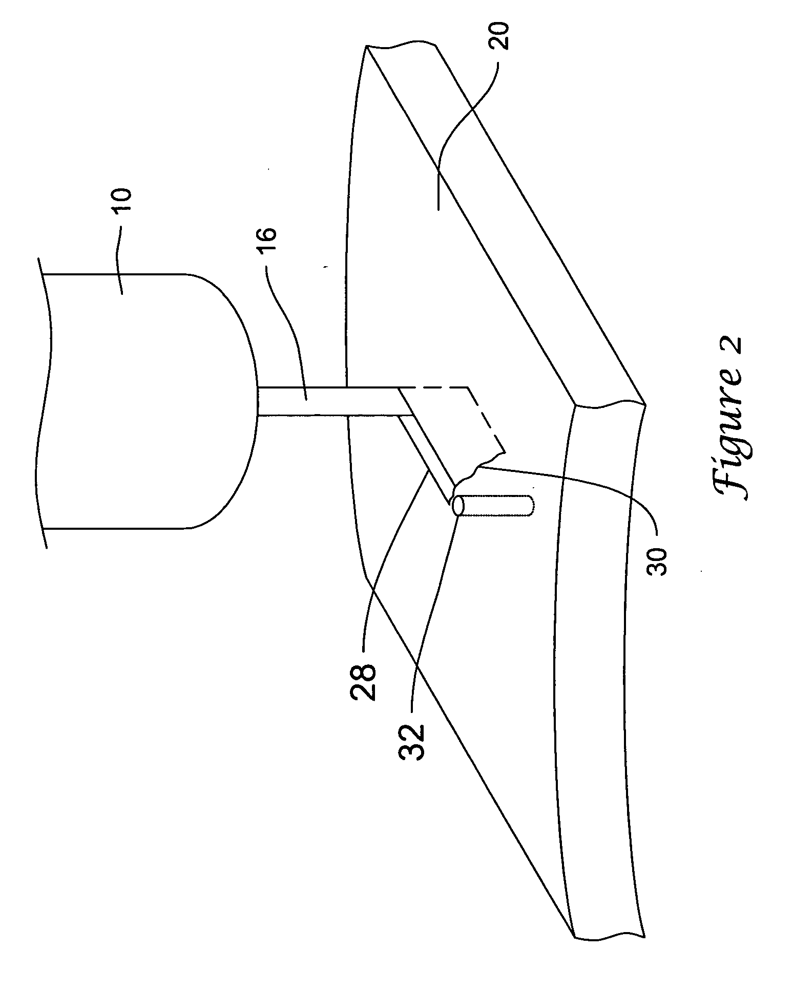
[0026] A hybrid liquid-jet / laser system may be used to cut or otherwise remove material from a tube or a flat sheet or web of material. A hybrid liquid-jet / laser system comprises a liquid stream, a low pressure stream, and a laser beam. The laser beam may be entrained within the liquid stream. When the hybrid stream containing both the ...


PUM

PropertyMeasurementUnit
Timeaaaaaaaaaa
Shapeaaaaaaaaaa
Areaaaaaaaaaaa

Abstract

A hybrid liquid-jet/laser device may be used to remove material from a tube or sheet to form a medical device, such as a stent. The liquid-jet/laser stream may be impinged against the wall of the tube or sheet between the ends of the tube or sheet, wherein an aperture may be formed in the tube or sheet, followed by a lead-in, and then a full thickness cut. A full thickness cut should be achieved via a lead-in before moving the liquid-jet/laser stream along a final cut path.

Description

BACKGROUND [0001] Implantable medical devices, such as a stents, grafts, stent-grafts, vena cava filters and the like, and delivery assemblies are utilized in a number of medical procedures and situations, and as such their structure and function are well known. [0002] Self-expanding, inflation expandable and hybrid stents are available in a variety of designs and configurations. Examples are disclosed in U.S. Pat. No. 6,348,065, U.S. 2002-0055770-A1 and U.S. Pat. No. 6,168,621, incorporated herein by reference. [0003] Stents are generally tubular but have been embodied in many different configurations and have been made of many materials, including metals and plastic. Ordinary metals such as stainless steel have been used, as have shape memory metals such as Nitinol and the like. Stents may also be made of bio-absorbable plastic materials. Stents may be formed from wire, flat sheets, tube stock, and the like. [0004] A number of techniques have been suggested for the fabrication of ...

Claims


Application Information

Patent Timeline
IPC IPC(8): A61F2/915B23K26/14
CPCB23K26/1417B23K26/146Y10T83/0596Y10T83/0591
Inventor KOCH, STEVEN J.
Owner BOSTON SCI SCIMED INC
Why Eureka
Try Eureka