Directionally oriented particle composites

a composite material and directional orientation technology, applied in the field of particle-based composite materials, can solve the problems of crystallographic orientation of particles, low saturation strain output of composite systems, and high cost of sonar transducers, and achieve the effects of reducing operating fields, improving the properties of particulate composite forms, and increasing saturation strain

Inactive Publication Date: 2005-07-28
RGT UNIV OF CALIFORNIA
View PDF4 Cites 18 Cited by
  • Summary
  • Abstract
  • Description
  • Claims
  • Application Information

AI Technical Summary

Benefits of technology

[0014] An illustrative embodiment of the invention is one that utilizes particles of the highly magnetostrictive compound, Terfenol-D (Th0.27Dy0.73Fe2). The magnetostriction of Terfenol-D is highly anisotropic with λ111=1600 microstrain and λ100=90 microstrain. As described in detail herein, a composite with [112] preferred orientation has been fabricated using the shape anisotropy orientation method described above. This composite exhibits a larger saturation strain than non-oriented composites and decreased operating fields. The increase in saturation magnetostriction over similar non-oriented magnetostrictive composites is 35-40%. This has improved the properties of the particulate composite form of magnetostrictive composites to near that of the commercially available form while simultaneously decreasing the electrical resistance by 2-4 orders of magnitude. The properties observed with magnetostrictive composites manufactured in this manner such as the reduction in resistance allows for a number of novel applications, for example their use in the operation of a vibrating device incorporating the magnetostrictive material at high frequency (10-100 kHz).

Problems solved by technology

This system has been employed to produce sonar transducers but is expensive and has a limited upper bound of frequency response (see, e.g. Butler et al., OCEANS 2000 MTS / IEEE Conference Proceedings, Providence R.I., pp.
However, all composite systems have thus far produced much lower saturation strain output than the comparable commercially available monolithic materials.
However, this process does not result in crystallographic orientation of the particles.
However, this compact is then sintered to produce a solid material, and not a composite material.

Method used


Image

  • Directionally oriented particle composites
  • Directionally oriented particle composites
  • Directionally oriented particle composites

Examples


example 1

Illustrative Example 1

A. Protocols

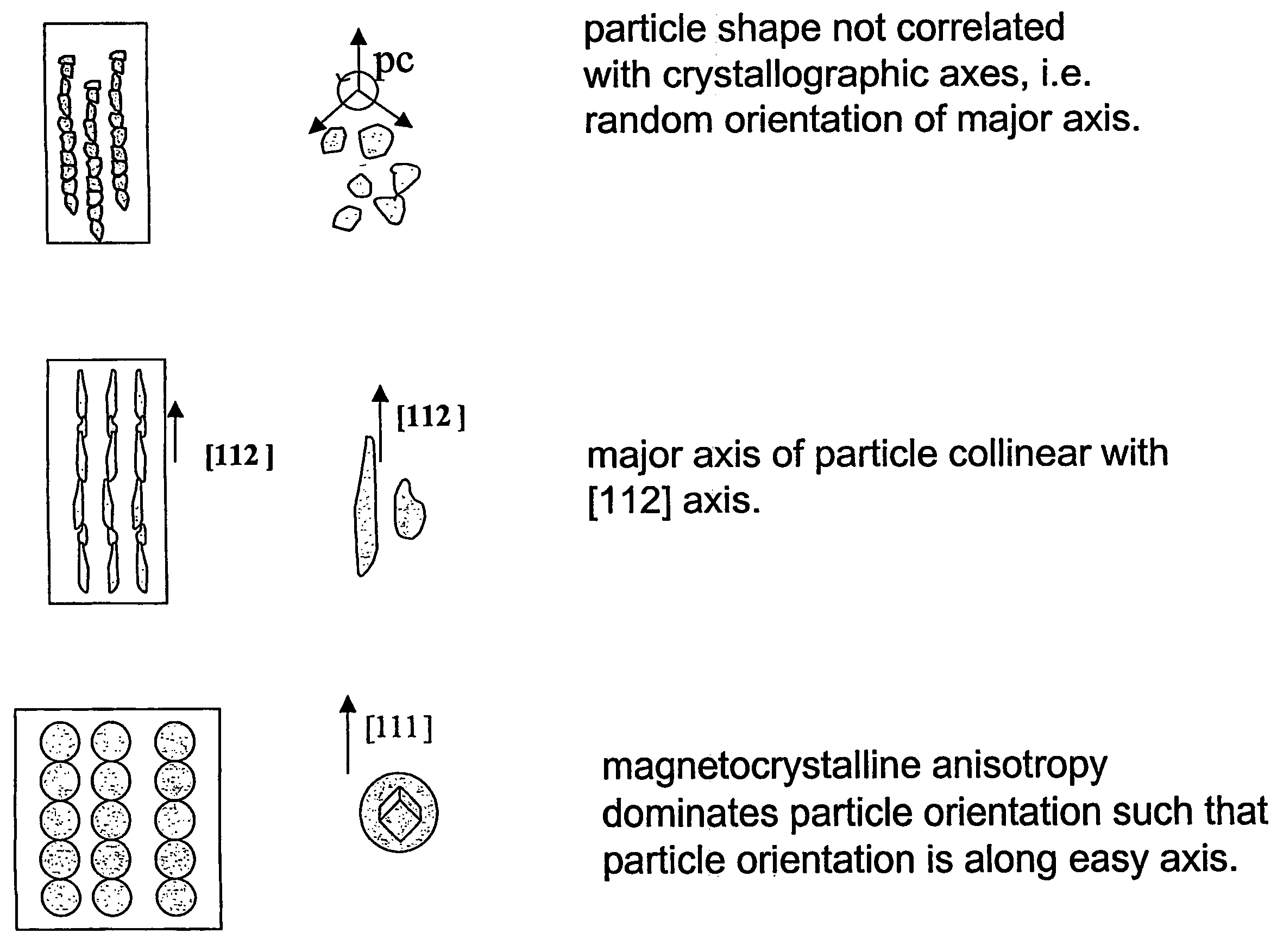
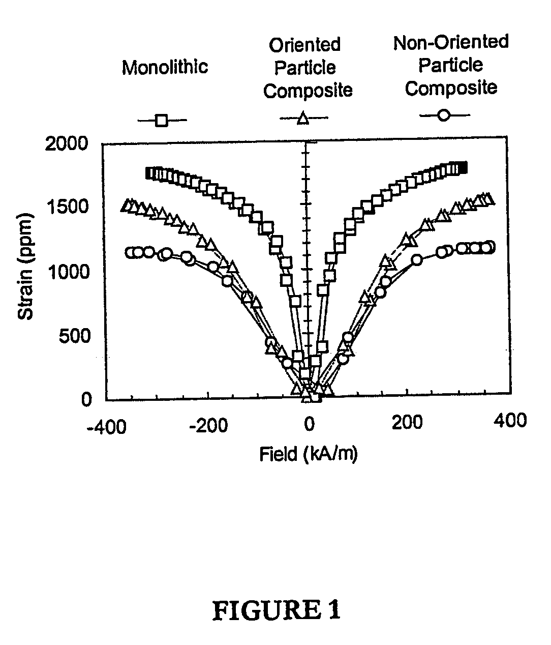
[0061] Two different types of composites (oriented and non-oriented) were manufactured for this example. The composites, along with a monolithic [112] Terfenol-D sample, were tested under combined magneto-mechanical loading at constant ambient temperature. Data recorded include load, strain, flux, and magnetic field. The research focus was to understand the role of crystallographic orientation on the magnetostriction in composite materials. In the following paragraphs, the fabrication and testing approach is described in detail.

[0062] In this example, particle crystal orientation along crystal direction was accomplished with particle shape anisotropy. Thus it was necessary to produce particle shapes that provided orientation along the desired crystallographic direction. For Terfenol-D this direction corresponds to the direction of maximum magnetostriction or the [111]. However, commercially available material is only produced with the orientation...

example 2

Illustrative Example 2

[0077] Skilled artisans will note a certain amount of overlap between the disclosure information that is provided in Example 1 and Example 2.

A. Protocols

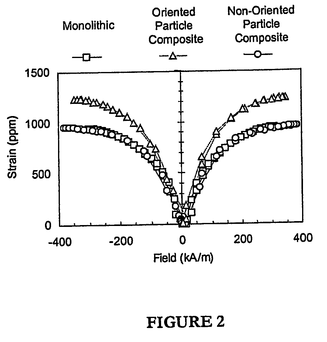
[0078] As in Example 1 above, in this Example, two different types of composites (oriented and non-oriented) were manufactured for this study. The composites, along with a monolithic [112] Terfenol-D sample, were tested under combined magneto-mechanical loading at constant ambient temperature. Data recorded include load, strain, flux, and magnetic field. In the following paragraphs, the fabrication and testing approach is described in detail.

[0079] In this study, particle orientation along a specific crystal orientation was accomplished using particle shape anisotropy. Thus needle shaped particles with the longest axis along a direction of high magnetostriction were necessary. In Terfenol-D the maximum magnetostriction orientation is the [111]. However, commercially available material is only produced with ...


PUM

PropertyMeasurementUnit
frequencyaaaaaaaaaa
frequencyaaaaaaaaaa
frequency responseaaaaaaaaaa

Abstract

Magnetostrictive particulate composites with a preferred crystal orientation of the particles and methods for their manufacture are described. In a representative embodiment, a 25% volume Terfenol-D fraction polymer matrix composite was fabricated in a magnetic field using geometric anisotropy to orient needle shaped particles with long axis [112] orientation along the length of the composite. Results demonstrate that the magnetostriction of a [112] oriented particle composite saturates near 1600 ppm. This is a significant increase when compared to composites without preferential orientation (1200 ppm) and represents the largest reported magnetostriction for a particulate composite material.

Description

RELATED APPLICATIONS [0001] This application claims priority under Section 119(e) from U.S. Provisional Application Ser. No. 60 / 360,470 filed Feb. 28, 2002, the contents of which are incorporated herein by reference.STATEMENT OF GOVERNMENT SUPPORT [0002] Portions of this work have been performed under the auspices of the National Science Foundation Grant No. CMS-9815208. The government may have certain rights to this invention.FIELD OF THE INVENTION [0003] The invention is in the area of particulate-based composite materials and methods for generating and using such materials. More specifically, the invention relates to magnetostrictive powder composites and methods for making such composites. BACKGROUND OF THE INVENTION [0004] Magnetostrictive composites typically comprise rare earth metals (RE) and transition metals (e.g. Fe, Ni, Co and Mn), (RE)xFe1-x, and exhibit a significant ability to change their length when exposed to an external magnetic field. In contrast to traditional m...

Claims


Application Information

Patent Timeline
Patent Type & Authority Applications(United States)
IPC IPC(8): B22F3/00B22F1/02B22F3/02B29C70/62H01F1/03H01F1/055H01F1/06H01F1/26H01L41/20H01L41/22H01L41/47
CPCB29C70/62B29K2995/0003B29K2995/0008B29K2995/0041H01L41/47H01F1/0558H01F1/063H01L41/20B29K2995/0044H10N35/85H10N35/01
Inventor MCKINGHT, GEOFFREY PCARMEN, GREGORY P.
Owner RGT UNIV OF CALIFORNIA
Why Eureka
Try Eureka