

Hysteresis comparator circuit
a comparator circuit and hysteresis technology, applied in the field of comparator circuits, can solve the problems of increasing the difficulty of adjusting the resistance of voltage dividing resistors, the accuracy of each resistance becomes worse, and the output will change frequently by that noise, so as to achieve the effect of hysteresis width
- Summary
- Abstract
- Description
- Claims
- Application Information
AI Technical Summary
Benefits of technology
Problems solved by technology
Method used
Image

Examples
first embodiment
[First Embodiment]
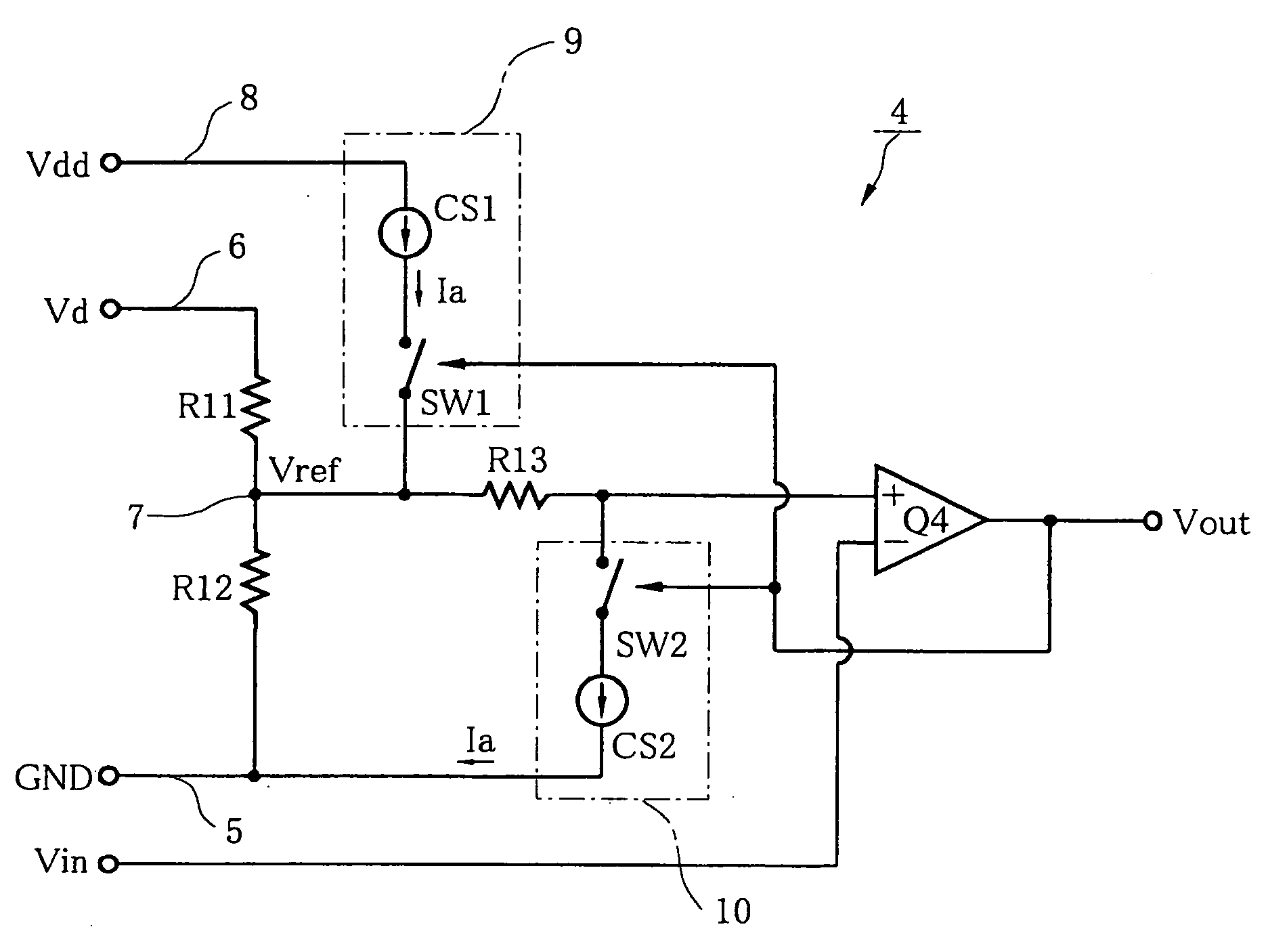
[0038] As shown in FIG. 1, a hysteresis comparator circuit 4 of a first embodiment is constructed with a comparator Q4, a resistor (first resistor) R11, a resistor (second resistor) R12, a resistor (third resistor) R13, a first constant current circuit 9 and a second constant current circuit 10.
[0039] The resistors R11 and R12 are connected in series between a potential reference line 5 connected to the reference potential GND (ground) and a first power line 6 for supplying a first constant voltage Vd applied from the outside, with the resistor R11 connected to the first power line 6. The resistor R13 is connected between the interconnection point 7 of the resistors R11 and R12 and a non-inverting input terminal (+) of the comparator Q4. An input voltage Vin is applied to the inverting input terminal (−) of the comparator Q4.
[0040] The comparator Q4 outputs a H-level voltage (for example, 5V) when a voltage applied to the non-inverting input terminal is equal to ...
second embodiment
[Second Embodiment]
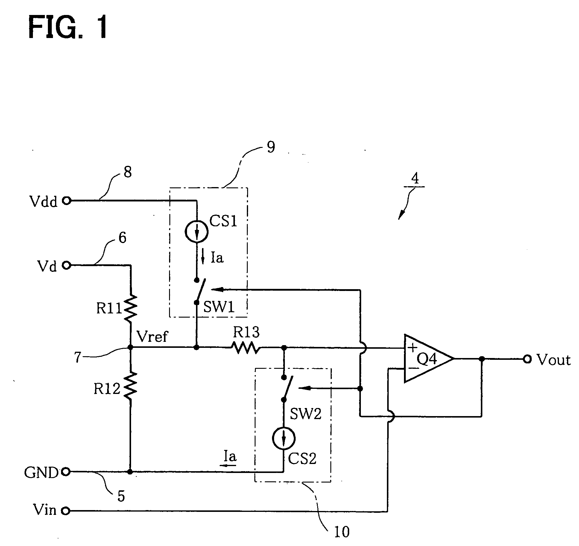
[0053] A hysteresis comparator circuit 4a of a second embodiment realizes a hysteresis comparator circuit having an input-output characteristic as shown in FIG. 16.
[0054] The circuit configuration of FIG. 2 differs from the circuit configuration of FIG. 1 in the following respects. A connection of one end of the resistor (third resistor) 13 is changed from a connection with the non-inverting input terminal of the comparator Q4 to a connection with the inverting input terminal. The input voltage Vin is applied to the non-inverting input terminal of the comparator Q4, not to the inverting input terminal. The constant current Ia supplied by the first constant current source circuit 9 is supplied to the inverting input terminal of the comparator Q4, not to the interconnection point 7.
[0055] A connection of the second constant current source circuit 10 is changed so as to allow the second constant current source circuit 10 to absorb the constant current Ia from the i...
third embodiment
[Third Embodiment]
[0062] A hysteresis comparator circuit 4b of a third embodiment is a circuit such that the first constant current source circuit 9 and the second constant current source circuit 10 in FIG. 1 (first embodiment) are replaced with constant current source circuits 9a and 10a shown in FIG. 3, respectively.
[0063] The constant current source circuit 9a is constructed with a first constant current source CS3, a diode D1 and a transistor (first NPN transistor) Tr4. The first constant current source CS3 and the diode D1 are connected in series between the second power line 8 and the interconnection point 7, with the first constant current source CS3 connected to the second power line, and with a cathode of the diode D1 connected to the interconnection point 7. The transistor Tr4 is connected between an anode of the diode D1 and the potential reference line 5.
[0064] A resistor R15 is connected between a base of the transistor Tr4 and an output terminal of the comparator Q4....
PUM
 Abstract
Description
Claims
Application Information