
Variable-frequency high frequency filter

Inactive Publication Date: 2005-07-28
NIHON DEMPA KOGYO CO LTD
View PDF3 Cites 12 Cited by
  • Summary
  • Abstract
  • Description
  • Claims
  • Application Information

AI Technical Summary

Benefits of technology

[0017] It is an object of the present invention to provide a frequency-variable high frequency filter configured to have a position of the voltage-displacement null point in a coplanar line resonator fixed to facilitate designing the filter and also configured to obviate lowering the Q value to improve the resonance characteristics.
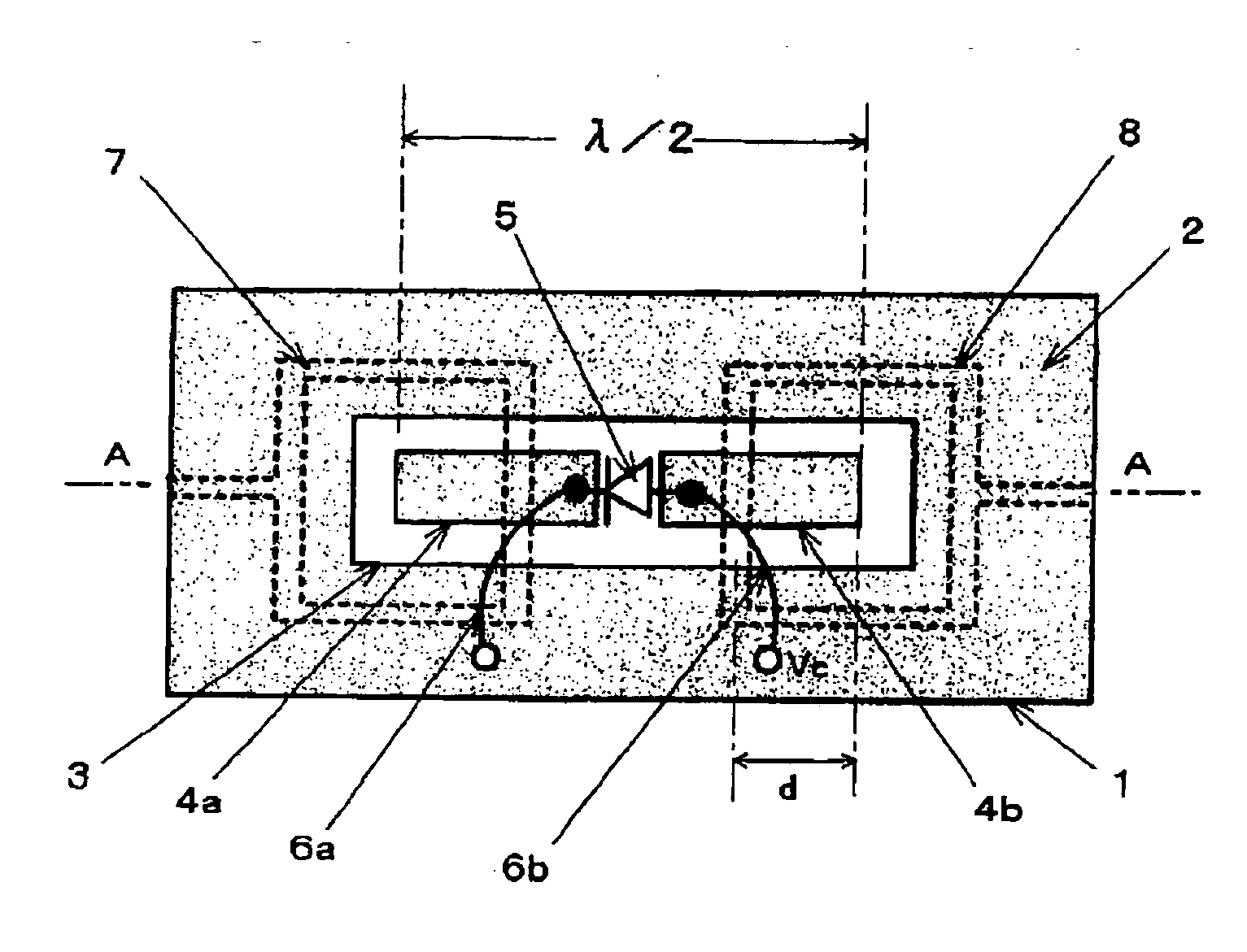
[0019] According to the present invention, it is enabled to make the resonance frequency of the filter variable through the use of the control voltage applied to a voltage-controlled variable reactance element, because the center conductor of the coplanar line resonator is divided at the null point of the voltage displacement, for example, at the middle point in the longitudinal direction of the center conductor, where the variable reactance element is connected. The influence of the provision of the variable reactance element and the circuitry to apply a control voltage to the variable reactance element on the resonance characteristic can be prevented, because the element and circuitry are arranged in the neighborhood of the null point of the voltage displacement in the standing wave. Nor, the control voltage causes the position of the null point in the voltage displacement to be displaced. For these reason, the present invention enables easily grasping the relation between the magnitudes of the variations in the control voltage and the resonance frequency and facilitating the designing of the filter and also enables realizing a low loss and high Q-value filter having a superior resonance characteristic.
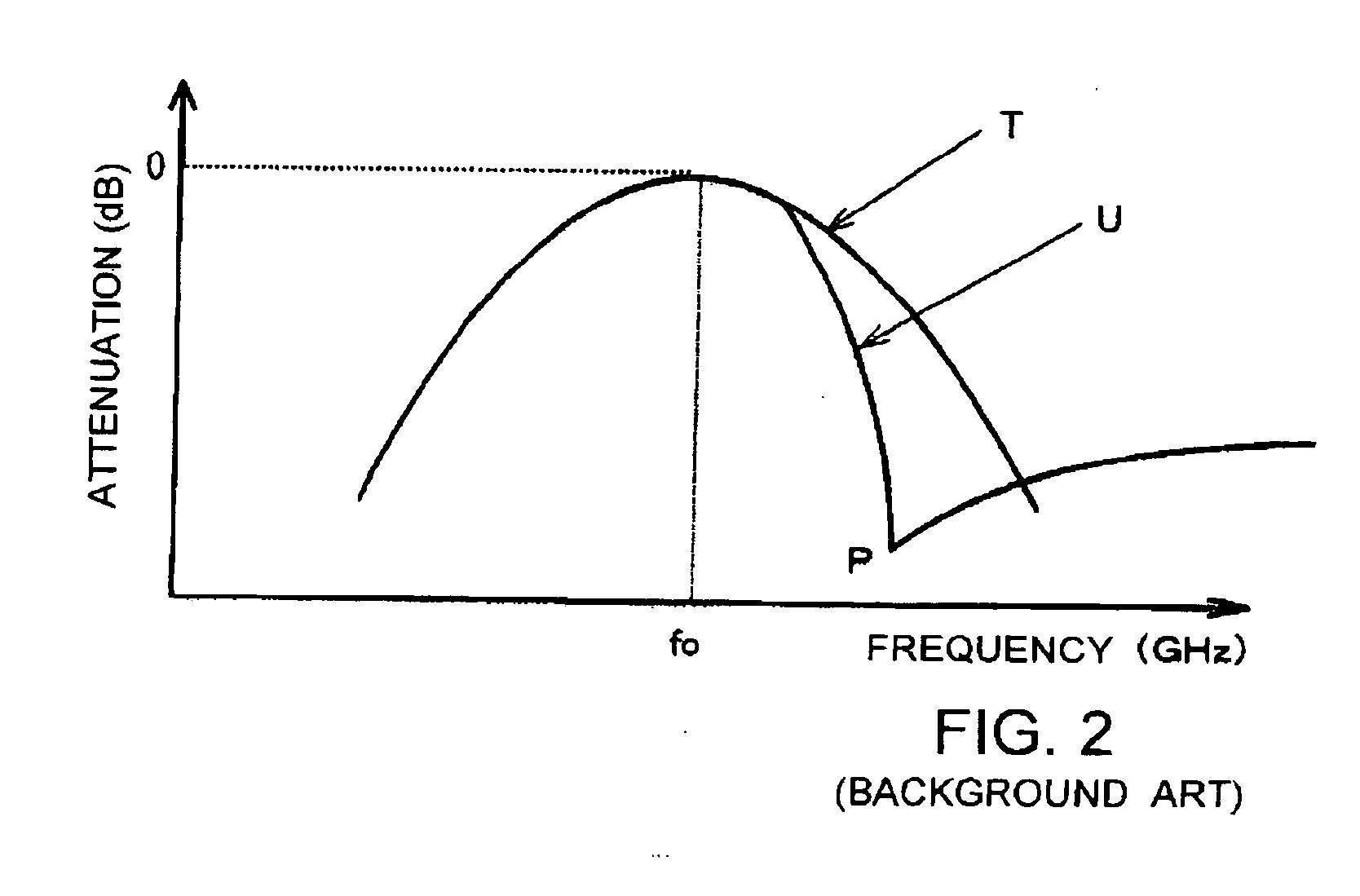
[0020] Furthermore, providing at least one of the input and output lines so as to traverse the center conductor yields an input / output resonance point at a frequency point higher than the resonance frequency of the coplanar line resonator to comply with the boundary condition, which enables establishing an attenuation pole on the high frequency side of the resonance frequency, thereby boosting the attenuation gradient on the high frequency side. Further, establishing the input / output resonance point makes it possible to realize a desired filter characteristic.

Problems solved by technology

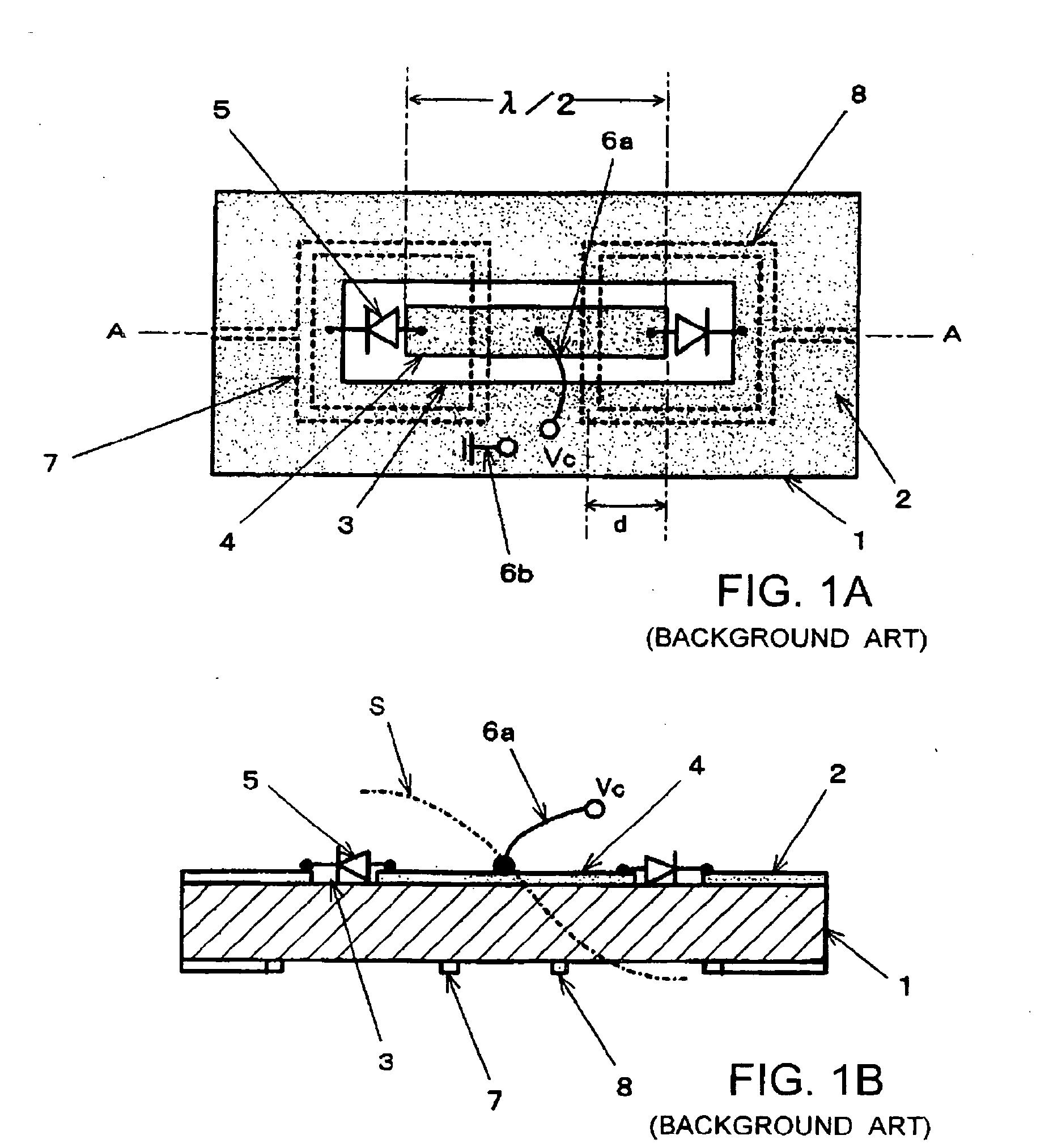
As a result, connection of supply line 6a affects the resonance characteristics of the resonator, which makes it difficult to design the resonator.
In addition, the deviation of the position of the null point from the middle point of the resonator brings about difficulty in the foregoing control of the frequency of the input / output resonance point, further entailing difficulty in designing a filter having desired attenuation characteristics.
Furthermore, in the case where the capacitance variation characteristics of the pair of variable capacitance diodes 5 against control voltage Vc are different, the balance with respect to the middle point of center conductor 4 is lost, entailing a loss.

Method used


Image

  • Variable-frequency high frequency filter
  • Variable-frequency high frequency filter
  • Variable-frequency high frequency filter

Examples


Embodiment Construction

[0031] In FIGS. 3A and 3B that illustrate a high frequency filter of a first embodiment according to the present invention, the constituent elements that are Identical to the constituent elements in FIGS. 1A and 1B bear the same reference numerals, and repeated explanation of such elements is simplified.

[0032] The high frequency filter illustrated in FIGS. 3A and 3B is a voltage-controlled high frequency filter of a frequency variable type, provided with a coplanar line resonator of a coplanar structure. Specifically, ground conductor 2 is provided on one of the principal surfaces of substrate 1 made of dielectric material, and rectangular opening 3 is formed in ground conductor 2. Center conductor 4 that extends in the longitudinal direction of opening 3 is provided in opening 3. Both ends of center conductor 4 are spaced apart from ground conductor 2. As with the case of a conventional high frequency filter shown in FIGS. 1A and 1B, input line 7 and output line 8 are provided on ...


PUM


Abstract

A frequency-variable high frequency filter comprises: a substrate; a ground conductor having an opening provided on one principal surface of the substrate; a center conductor provided in the opening to make up a coplanar line resonator with the substrate and the ground conductor; an input line and an output line provided on the other principal surface of the substrate and electromagnetically coupled with the center conductor; and a variable reactance element. The center conductor is divided into two conductor section at the position of the null point of the voltage displacement of a standing wave created in the coplanar line resonator so that the two conductor sections are separated in the longitudinal direction of the center conductor. The variable reactance element is inserted in the center conductor to connect the two conductor sections of the center conductor.

Description

BACKGROUND OF THE INVENTION [0001] 1. Field of the Invention [0002] The present invention relates to a high frequency filter employed in the ultra high frequency band (approximately 1 to 100 GHz) covering the frequency range such as microwave and millimeter-wave bands, and particularly to an easily designable, variable-frequency high frequency filter adapted to use a coplanar line resonator and capable of electronically controlling the filter characteristics such as a transmission characteristic, particularly a band characteristic or the like. [0003] 2. Description of the Related Arts [0004] A high frequency filter has been widely employed as a functional element imperative for injection and extraction of a desired signal and also suppression and elimination of unwanted signals in transmission and reception apparatuses, in a variety of radio communication facilities, optical fiber high-speed transmission apparatuses and measuring instruments related to the above apparatuses. [0005] ...

Claims


Application Information

Patent Timeline
IPC IPC(8): H01P1/201H01P1/203H01P1/205H01P7/08
CPCH01P1/2013
Inventor ASAMURA, FUMIO
Owner NIHON DEMPA KOGYO CO LTD
Learn More