
Apparatus and method of information extraction from electromagnetic energy based upon multi-characteristic spatial geometry processing

a technology of electromagnetic energy and information extraction, applied in the field of apparatus and method of information extraction from electromagnetic energy based upon multi-characteristic spatial geometry processing, can solve the problems of inability to maintain two-dimensional spatial integrity of source objects, inability of spectrometers to determine spectral content pixel-by-pixel, and certain limitations imposed by the geometry of these systems

Active Publication Date: 2005-07-28
PHOTON
View PDF64 Cites 17 Cited by
  • Summary
  • Abstract
  • Description
  • Claims
  • Application Information

AI Technical Summary

Problems solved by technology

Such a standard spectrometer is an excellent device for determining the spectral composition of light emanating from a source object, but is unable to maintain two-dimensional spatial integrity of the source object.
Typically, such a spectrometer is not capable of determining spectral content on a pixel-by-pixel basis, and merely collects the total intensity of electromagnetic energy proceeding from an object.
However, there are certain limitations imposed by the geometry of these systems.
For example, in both types of systems, field of view of is severely restricted.
Therefore, the number of pixels that can be acquired is limited.
Consequently, as the light undergoes multiple reflections, it will “walk” along the mirrors and eventually leak out of the cavity.
The second problem that results in a limitation of the field of view for the Fabry-Perot system has to do with band pass variation with field size.
However, this will again limit the number of pixels that can be obtained.
Still another problem that can arise with respect to some known systems, such as the Fourier transform interferometer, deals with image registration.
Problems associated with scanning, such as mirror jitter, uneven scanning, or mirror walking, create registration problems between the images in the different spectral bands.
During such scanning, it difficult to obtain the spectral composition in real-time while maintaining a high signal-to-noise ratio.
This is not only a problem for the Fourier transform and Fabry-Perot interferometers, but also for electrically scanned systems such as liquid crystal systems and acousto-optic tunable filter based imaging spectrometers, which have the additional problem of relatively low transmission.
However, the downside of this technique is that it is computationally intensive, requiring the mathematically determination of a system matrix, which is usually application specific.
None have been successful in providing an operation device that has abilities greater than a two channel orthogonal system.
The rotating analyzer limits the system to static scenes and is not a useful tool for spatial phase analysis.
Another problem that arises for imaging systems that employ moving components, such as a rotating member, deals with the issue of image registration.
However, problems associated with rotating, such as optical wedge wobbling, uneven rotating, or beam walking, create registration problems between the images in the different phase channels.
Rotating systems will vary the angular extent of the object and cannot be used effectively.
Therefore, while some of the prior art is capable of performing limited polarimetry and other intensity-based applications, it is not capable, for the reasons discussed, of providing true, multi-dimensional, real-time spatial phase imaging.

Method used


Image

  • Apparatus and method of information extraction from electromagnetic energy based upon multi-characteristic spatial geometry processing
  • Apparatus and method of information extraction from electromagnetic energy based upon multi-characteristic spatial geometry processing
  • Apparatus and method of information extraction from electromagnetic energy based upon multi-characteristic spatial geometry processing

Examples


Embodiment Construction

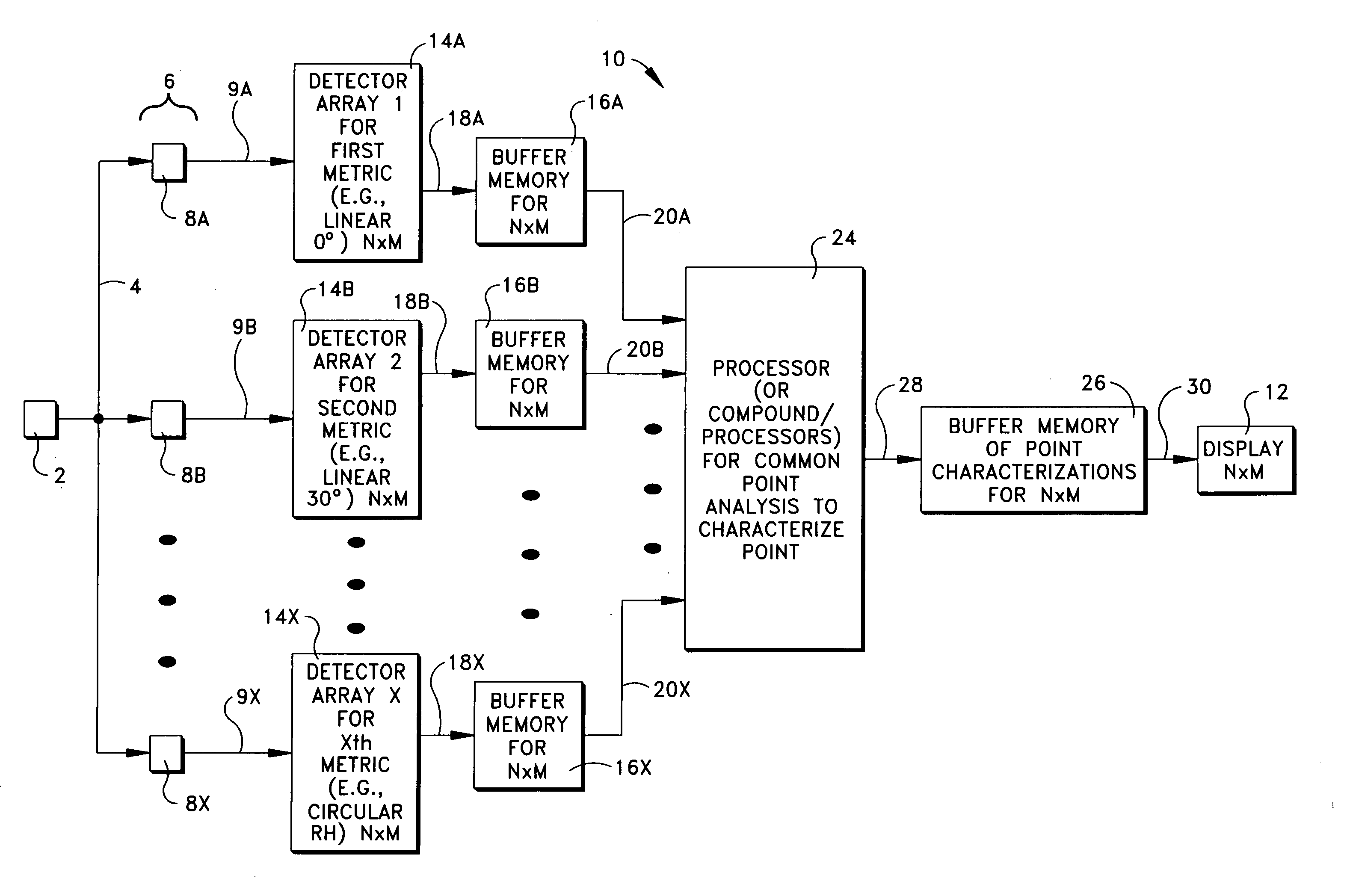
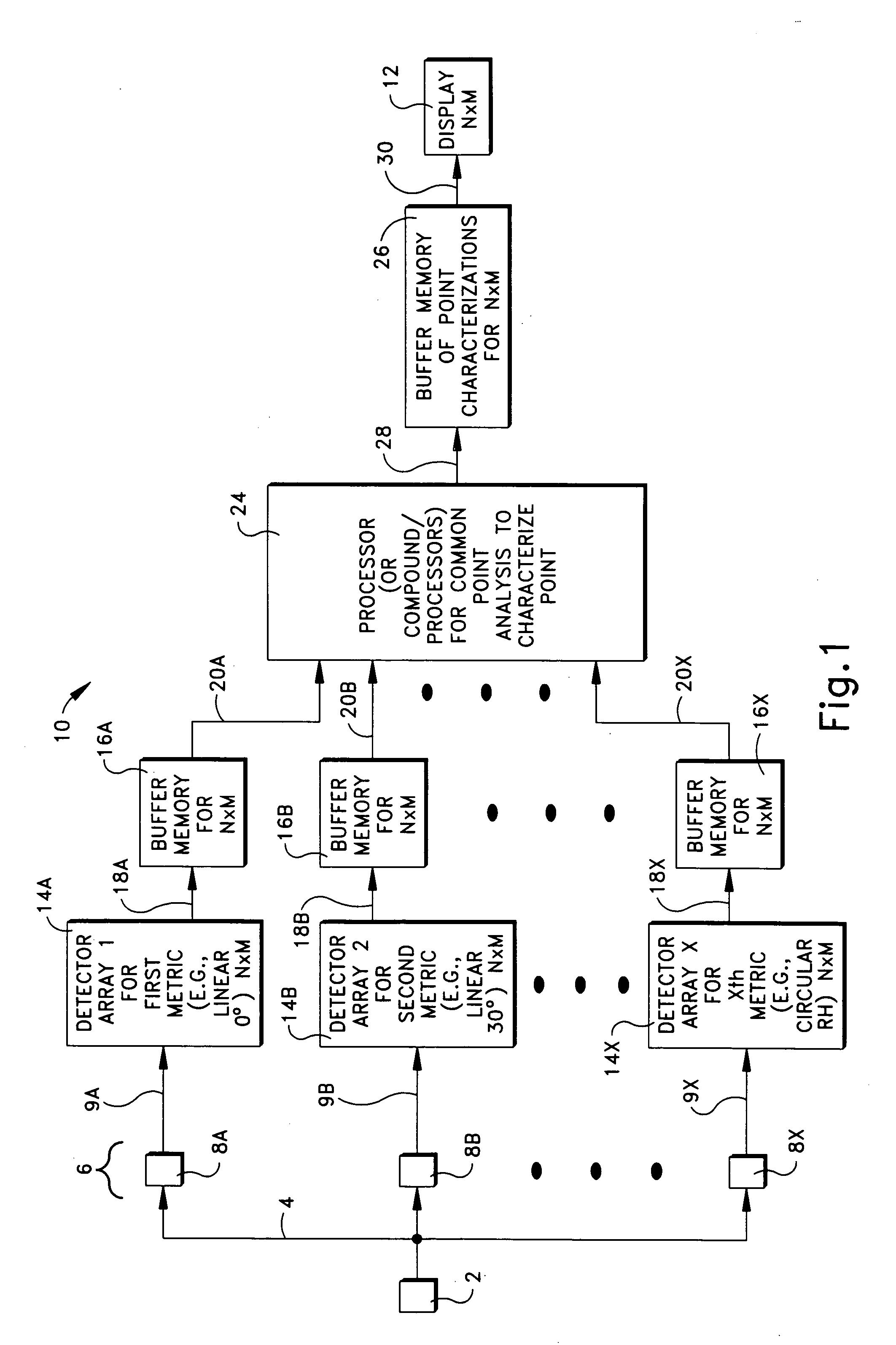
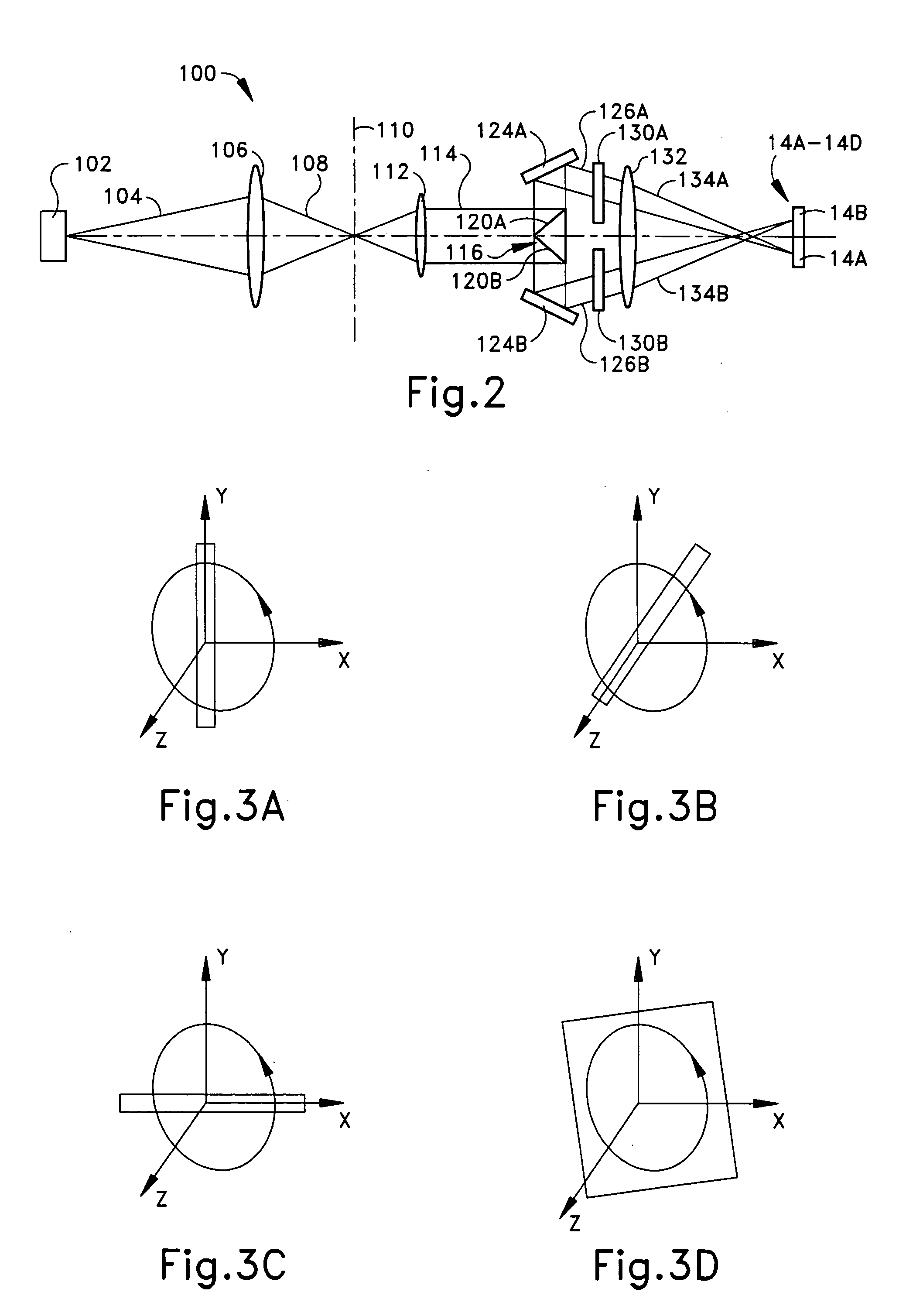
[0040] As light propagates and interacts with a surface of an object, the light will be absorbed, reflected, transmitted or emitted back off the surface. It has been appreciated by the inventor that the properties of the light proceeding from the surface contain all the characteristics regarding that object (surface). The characteristics include the object material type, molecular structure (which is a huge factor in what is absorbed and reflected), structure of the molecular elements, orientation of the surface, spectral content, intensity (which is changed by amounts of absorption and reflection), and of coarse polarization of the reflected or emitted light. Within some of the inventor's previous work (see U.S. Pat. No. 5,890,095) there was attention given to benefits which could be developed directly from the classical polarization elements, which only deals with the reflected and emitted components of the light and only deals with the orthogonal s- and p-polarizations. The prese...


PUM


Abstract

An apparatus for information extraction from electromagnetic energy via multi-characteristic spatial geometry processing to determine three-dimensional aspects of an object from which the electromagnetic energy is proceeding. The apparatus receives the electromagnetic energy. The received electromagnetic energy has a plurality of spatial phase characteristics. The apparatus separates the plurality of spatial phase characteristics of the received electromagnetic energy. The apparatus r identifies spatially segregated portions of each spatial phase characteristic, with each spatially segregated portion of each spatial phase characteristic corresponding to a spatially segregated portion of each of the other spatial phase characteristics in a group. The apparatus quantifies each segregated portion to provide a spatial phase metric of each segregated portion for providing a data map of the spatial phase metric of each separated spatial phase characteristic. The apparatus processes the spatial phase metrics to determine surface contour information for each segregated portion of the data map.

Description

RELATED APPLICATIONS [0001] This application claims the benefit of U.S. patent application Ser. No. 09 / 621,768, filed Jul. 21, 2000, which claims benefit of U.S. Provisional Application No. 60 / 145,017, filed Jul. 22, 1999, U.S. Provisional Application No. 60 / 145,194, filed Jul. 23, 1999, and U.S. Provisional Application No. 60 / 145,264, filed Jul. 26, 1999.FIELD OF THE INVENTION [0002] The present invention is directed to an apparatus and method that extracts and exploits information conveyed within spatial phase (e.g., three-dimensional geometry) characteristics of electromagnetic energy (e.g., light), and is particularly directed to apparatus and method that extracts data from multi-characteristic spatial phase processing as a novel approach to providing information useful for imagery and the like. BACKGROUND OF THE INVENTION [0003] Conventional imaging systems employ intensity-based techniques to handle electromagnetic energy proceeding from a source (e.g., an object). As one exam...

Claims


Application Information

Patent Timeline
IPC IPC(8): G01B11/24G01J3/28G01J3/36G01J3/447G01J4/04G01J9/00G06K7/00G06K9/00G06K9/36H01Q3/26
CPCG01B11/24G01J3/2823G01J3/36G01J2009/002G01J4/04G01J9/00G01J3/447
Inventor BARBOUR, BLAIR A.
Owner PHOTON
Learn More