Apparatus for applying spin to optical fiber and optical fiber manufacturing method and apparatus using the same

a technology of optical fiber and manufacturing method, applied in the field of manufacturing optical fibers, can solve the problems of serious deterioration of the regularity of coatings, and achieve the effect of easy control and easy manufactur

Inactive Publication Date: 2005-07-28
LG CABLE LTD (KR)
View PDF8 Cites 11 Cited by
  • Summary
  • Abstract
  • Description
  • Claims
  • Application Information

AI Technical Summary

Benefits of technology

[0037] In addition, the present invention also provides an optical fiber manufacturing apparatus in which the above-mentioned spin applying apparatus is arranged between a coating device and a take-up bobbin. With this configuration, the present invention allows easy manufacture of an op

Problems solved by technology

However, increasing the moving velocity or amplitude of the roller has various limitations, and particularly the increase of the ampl

Method used


Image

  • Apparatus for applying spin to optical fiber and optical fiber manufacturing method and apparatus using the same
  • Apparatus for applying spin to optical fiber and optical fiber manufacturing method and apparatus using the same
  • Apparatus for applying spin to optical fiber and optical fiber manufacturing method and apparatus using the same

Examples


Embodiment Construction

[0049] Hereinafter, preferred embodiments of the present invention will be described in detail with reference to the accompanying drawings.

[0050]FIG. 3 shows a schematic configuration of an optical fiber manufacturing apparatus 100 according to the present invention.

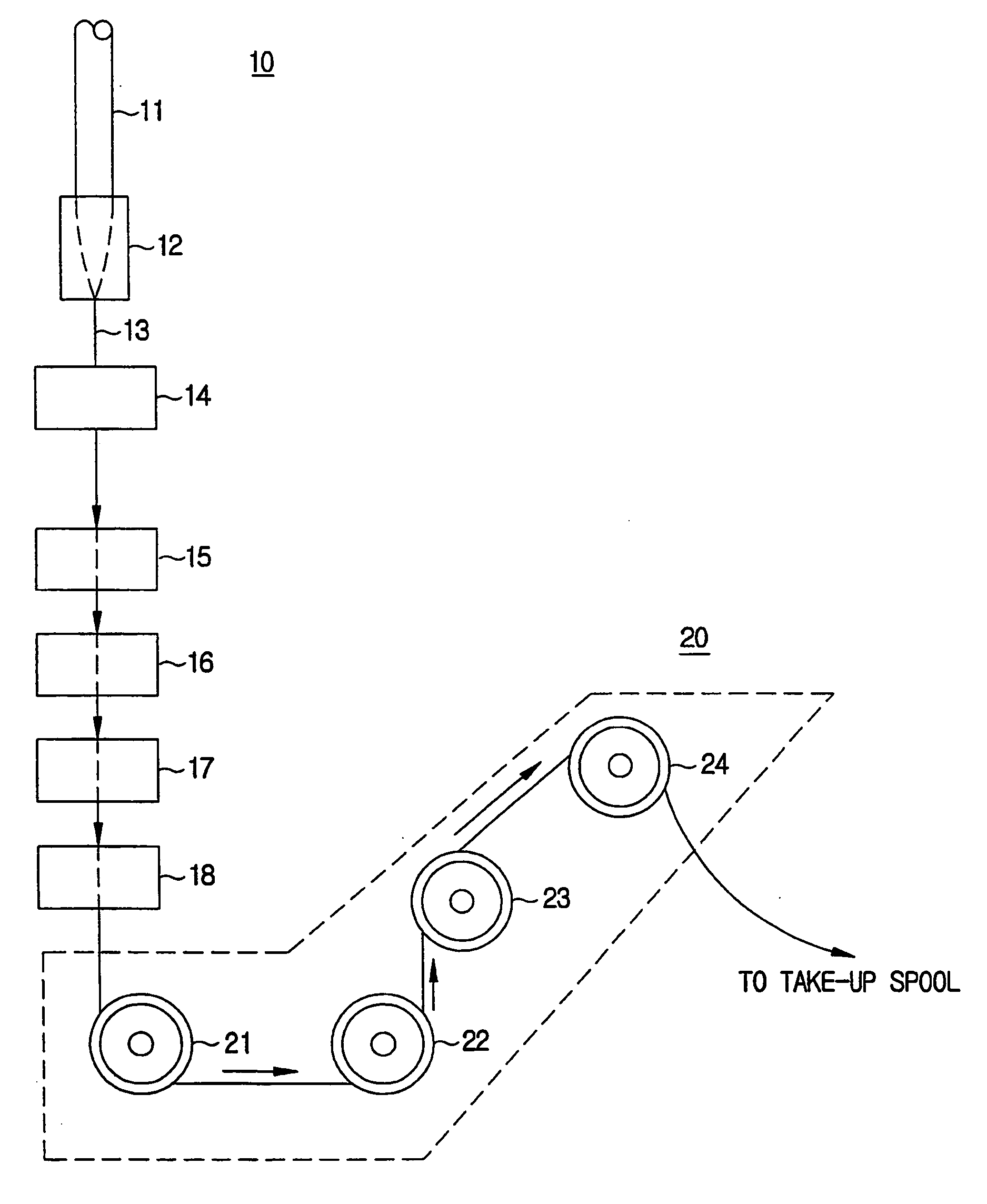
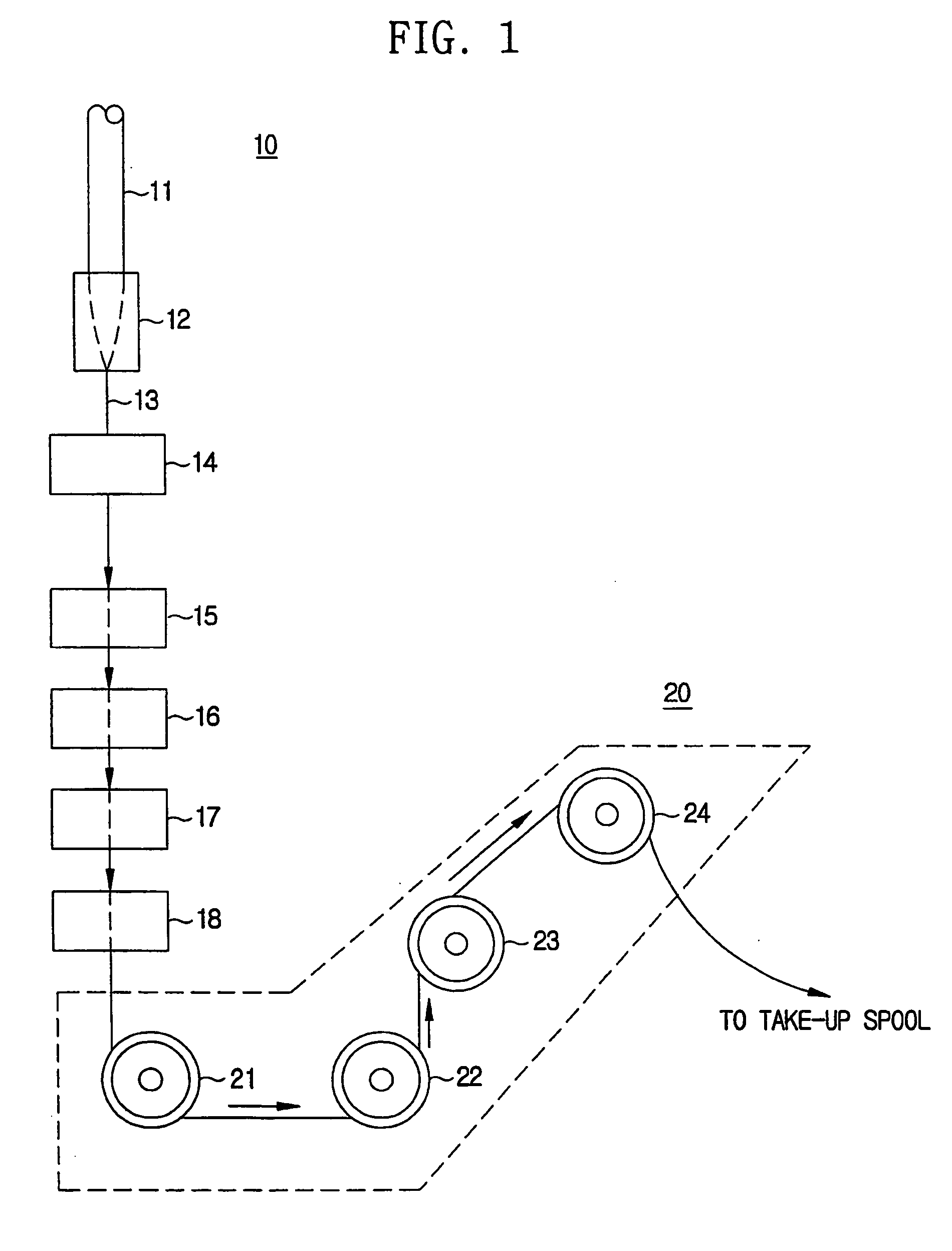
[0051] The optical fiber manufacturing apparatus 100 heats an optical fiber preform 101 in a furnace 102 to a high temperature, and then draws a bare optical fiber 103 from a neck-down portion of the preform which is softened. The drawn bare optical fiber 103 is passing through an outer circumference measurer 104 and cooled in a cooling device 105, and then coated with an ultraviolet hardening resin at least one time in a coating device 106. The coated optical fiber coated in the coating device 106 is then hardened in a hardening device 107 and then transferred to a spin applying device 110.

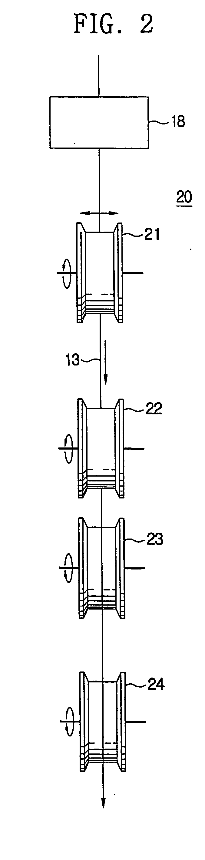
[0052] The optical fiber is twisted with a predetermined spin rate in the spin applying device 110 and then traveled through a dr...


PUM

PropertyMeasurementUnit
Angleaaaaaaaaaa
Diameteraaaaaaaaaa
Radiusaaaaaaaaaa

Abstract

A method of applying spin to a coated optical fiber to be rotated on its longitudinal axis so that the optical fiber has an ultra-low PMD (Polarization Mode Dispersion) includes the steps of: guiding the coated optical fiber so as not to be deviated from a certain range off a drawing axis at a lower end of an optical fiber coating point; giving torque to the optical fiber by contacting the coated optical fiber with a driving roller which vibrates on the center of an axis substantially parallel to a drawing direction at a lower end of the guiding point; and adjusting an amplitude (A) of the driving roller and a distance (l) between the guiding point and the vibrating point so as to control an angle (θ) between the vibrating optical and the drawing axis. This makes it possible to control a spin rate (spins/m) of the optical fiber generated by rotation.

Description

TECHNICAL FIELD [0001] The present invention relates to manufacturing an optical fiber, and more particularly to method and apparatus for applying a spin to an optical fiber in order to manufacturing an optical fiber having an ultra-low Polarization Mode Dispersion (PMD). BACKGROUND ART [0002] A single mode optical fiber with a circular symmetric structure theoretically has two orthogonal polarization modes which are independent and compensated each other. Generally, an electric field of the light propagating through an optical fiber can be considered as linear overlap of such two peculiar polarization modes. In the single mode optical fiber in fact, compensation of the two polarization modes is generated due to defective factors such as symmetric lateral stress or eccentricity of a circular core. These two modes are propagated at different phase rates, hence two modes have different propagation constants (β1 and β2). This difference of propagation constants is called double refract...

Claims


Application Information

Patent Timeline
IPC IPC(8): C03B37/027G02B6/00C03B37/03C03B37/12
CPCC03B37/02745C03B37/032C03B2205/06C03B2203/36C03B2203/19G02B6/00
Inventor KWON, YOUNG-ILBAE, SANG-JOONLEE, JOON-KEUNJANG, MYUNG-HOLEE, BONG-HOON
Owner LG CABLE LTD (KR)
Why Eureka
Try Eureka