Thin sheet mirror and Nd2O3 doped glass

Inactive Publication Date: 2005-07-28
CORNING INC
View PDF5 Cites 0 Cited by
  • Summary
  • Abstract
  • Description
  • Claims
  • Application Information

AI Technical Summary

Benefits of technology

[0013] The present invention has the advantage of improved, more desirable light transmission properties, such th

Problems solved by technology

A problem of long standing is that of visual discomfort, and loss of object definition, created by reflection of certain radiation.
The reflection of illumination from a mirror, particularly a

Method used


Image

  • Thin sheet mirror and Nd2O3 doped glass
  • Thin sheet mirror and Nd2O3 doped glass
  • Thin sheet mirror and Nd2O3 doped glass

Examples


Example

[0019] The present invention provides a reflecting mirror, particularly a rearview mirror, in which the visual discomfort and blurring, caused by reflected illumination or sunlight, are alleviated. Such mirrors are widely used in all types of transport vehicles. However, the problem is particularly prevalent in rearview mirrors for automotive vehicles. Accordingly, the invention is described with respect to such application.

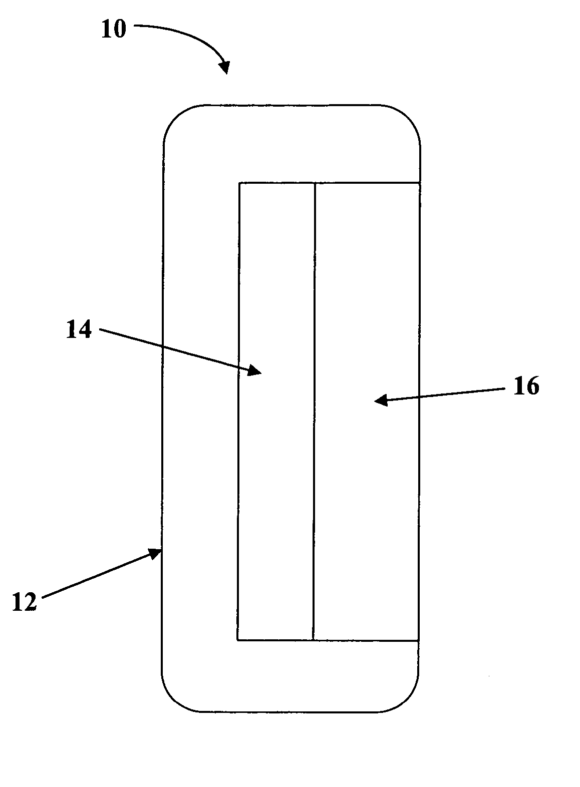
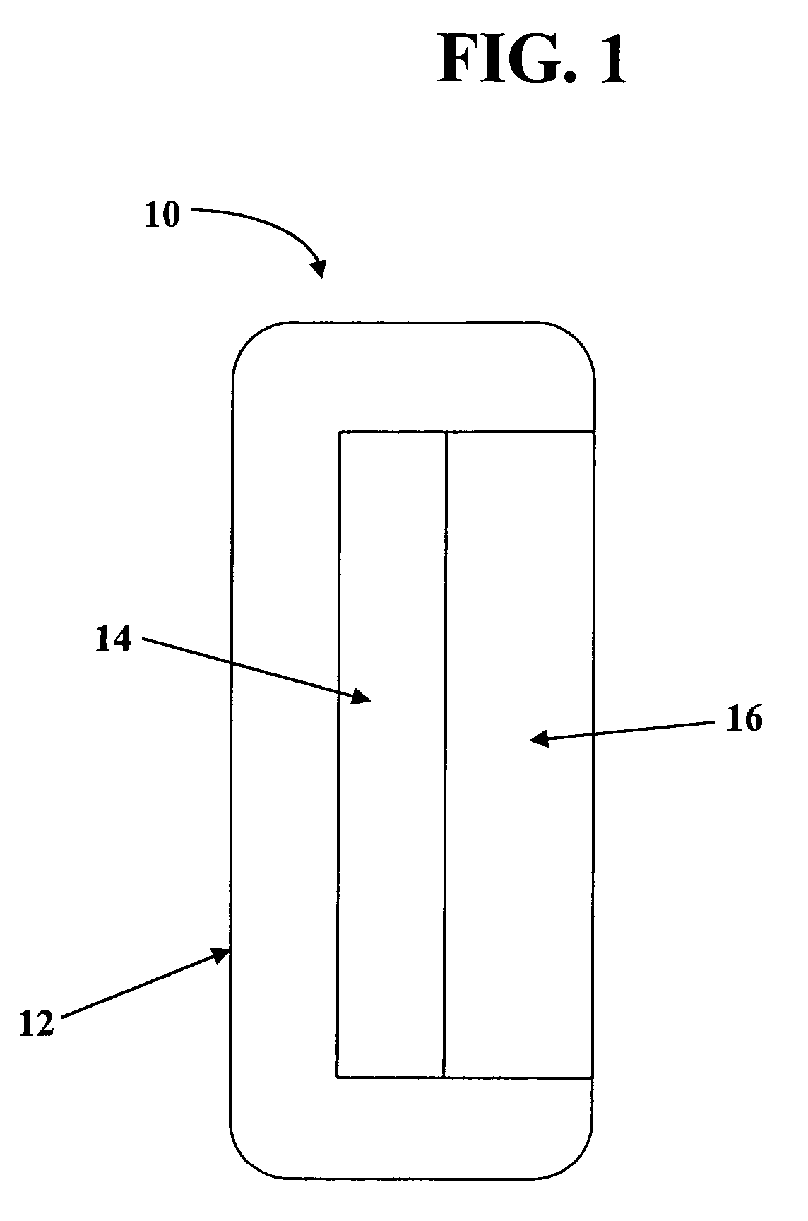
[0020]FIG. 1 is a side elevational view of a typical rearview mirror embodying the invention, and generally designated 10. Mirror 10 comprises a standard casing or enclosure 12 and a microsheet glass member 16 having a reflecting surface 14, e.g., a silver film on its rear surface. Glass member 16 may be bonded to casing 12 in known manner. One such structure is shown in U.S. Pat. No. 5,566,031.

[0021] The present invention is largely concerned with microsheet glass member 16. As pointed out earlier, microsheet glass is less than 0.5 mm in thickness. For present...


PUM

PropertyMeasurementUnit
Temperatureaaaaaaaaaa
Lengthaaaaaaaaaa
Lengthaaaaaaaaaa

Abstract

A reflecting mirror comprising a sheet of an alkali metal-zinc-borosilicate glass bonded to a reflecting surface, the glass sheet having a thickness less than 0.5 mm, and being doped with Nd2O3 in an amount sufficient to substantially reduce the spectral transmission of the glass in the wavelength range of 565-595 nm, and further doped with CO3O4 in the amount of 10-100 ppm, preferably 20-80 ppm, more preferably 30-60 ppm to reduce the pink hue of the glass.

Description

CROSS-REFERENCE TO RELATED APPLICATION [0001] This application is a continuation-in-part application of U.S. patent application Ser. No. 10 / 016,840 filed on Dec. 13, 2001 by Ronald R. Stewart, entitled “Thin Sheet Mirror and Nd2O3 Doped Glass,” which, in turn, claims the benefit of U.S. Provisional Application Ser. No. 60 / 255,759, filed on Dec. 15, 2000, entitled “Thin Sheet Mirror and Nd2O3 Doped Glass.”FIELD OF THE INVENTION [0002] A reflecting mirror comprising a thin sheet of glass, and an alkali metal-zinc-borosilicate glass doped with neodymium oxide (Nd2O3) and adapted to be drawn in the form of a thin sheet. BACKGROUND OF THE INVENTION [0003] Thin sheet glass, commonly referred to as microsheet, is well known in the glass art. The glass sheets have a thickness less than 0.5 mm, a standard thickness being in the range of 0.3 to 0.4 mm. Microsheet glass is used for such diverse purposes as protective covers for satellite solar cells, laptop LCDs, and glass-plastic laminates. [...

Claims


Application Information

Patent Timeline
IPC IPC(8): C03C3/095G02B5/08
CPCG02B5/08C03C3/095
Inventor STEWART, RONALD LEROY
Owner CORNING INC
Why Eureka
Try Eureka