Rotary tool and its cutting part

Inactive Publication Date: 2005-07-28
SANWA KENMA
View PDF12 Cites 62 Cited by
  • Summary
  • Abstract
  • Description
  • Claims
  • Application Information

AI Technical Summary

Benefits of technology

[0023] Further, if the rotary tool comprises at least first cutting parts having tips made of the sintered material and second cutting parts having tips made of the grinding tool segment, and the second cutting parts are arranged such that the tips thereof are locate

Problems solved by technology

On the other hand, the radially inner part of the tip, i.e. a part thereof performing less cutting work due to its lower peripheral speed, is made of the grinding tool segment (

Method used


Image

  • Rotary tool and its cutting part
  • Rotary tool and its cutting part
  • Rotary tool and its cutting part

Examples


first embodiment

[0035] the present invention is described with reference to the accompanying drawings. Although a case where a film applied to the outer surface of a work surface S is to be removed is illustrated in this embodiment, working according to the present invention is not limited thereto. The present invention is also widely applicable to removal of other “films” such as adhesives, resin sheets and resin tiles adhered to work surfaces or work surfaces made of other materials.

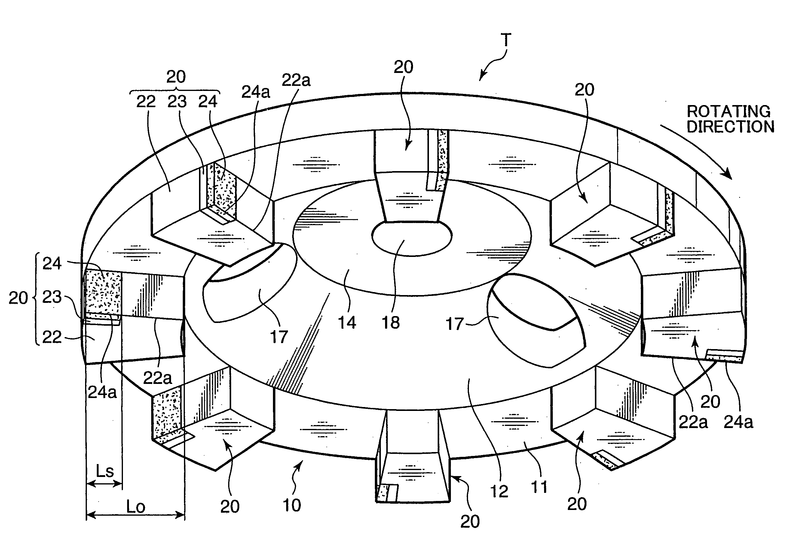
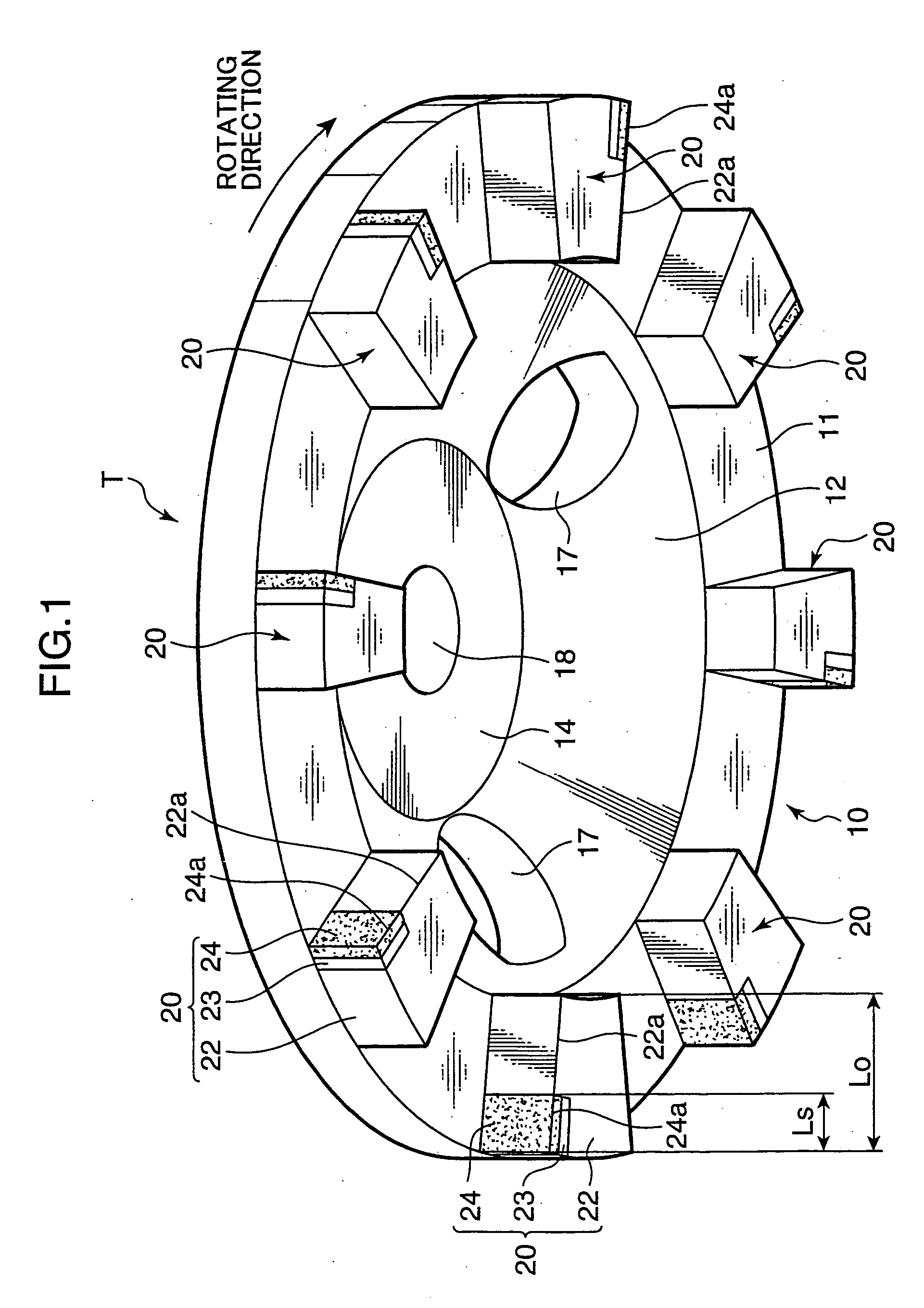
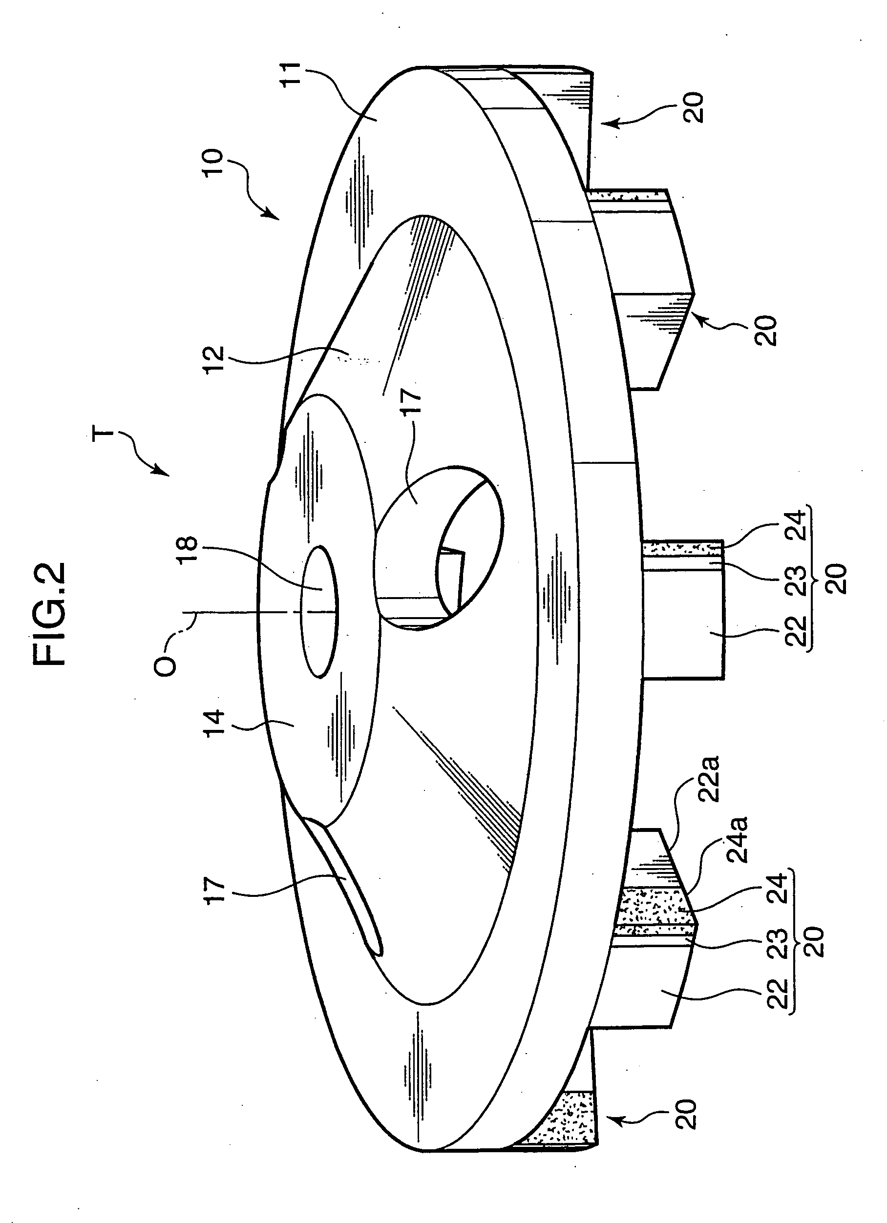
[0036] A rotary tool T shown in FIGS. 1 to 4 is comprised of a rotary segment 10 made of a metallic plate and a plurality of cutting parts 20 mounted on the rotary segment 10.

[0037] The rotary segment 10 integrally includes an outer peripheral portion 11 in the form of a flat plate 11 and an inner portion 12 formed inside the outer peripheral portion 11.

[0038] The inner portion 12 bulges out upward substantially in the form of a cone from the inner edge of the outer peripheral portion 11, and a flat portion 14 paral...

fourth embodiment

[0063] Specifically, as shown in FIG. 10 as a fourth embodiment, even in such a construction that cutting parts each including only the hard sintered material tip 24a are provided at positions radially more outward than the cutting parts 26 (cutting parts made by the hard sintered materials 24 are secured in recesses 16 formed in the opposed surface of the rotary segment 10 in the shown example), i.e. even in such a construction that the grinding tool segment tips 22a shown in FIG. 1 and other figures are deleted, the tips 26a of the cutting parts 26a made of the grinding tool segment can suppress excessive cutting-in, assist cutting by the tips 24a and grind off or finish scratches caused by the cutting by the tips 24a.

fifth embodiment

[0064] Further, as shown in FIG. 11 as a fifth embodiment, the rotary tool may be such that a grinding tool segment 28 having a shape continuous along a peripheral direction of the rotary segment 10 (ring shape in the shown example) is provided, and cutting parts each including the hard sintered material tip 24a are provided at positions more outward than this grinding tool segment 28 with respect to the radial directions of the rotary segment 10. In this way, even if the grinding tool segment 28 has no tip, it can assist the cutting by the hard sintered material tips 24a by its abrading action, and the abrasion thereby can grind off or finish scratches formed by cutting by the hard sintered material tips 24a. Of course, an effect of preventing excessive cutting-in can also be given.

[0065] However, if all the cutting parts are those according to the present invention and peripherally arranged at even intervals as in the first embodiment, cutting ability can be made uniform along per...


PUM


Abstract

A rotary tool (T) has a rotary segment (10) with an opposed surface opposed to a work surface and a plurality of cutting parts (20) arranged on the opposed surface. Some cutting parts (20) include tips (22a) made of a grinding tool segment obtained by binding abrasive grains by a metal binder and the other cutting parts (20) include tips (24a) made of a sintered material harder than the grinding tool segment, and the respective cutting parts (20) are arranged such that the tips (24a) are located at positions more outward than the tips (22a) with respect to radial directions of the rotary segment.

Description

TECHNICAL FIELD [0001] The present invention relates to a rotary tool and a cutting part thereof for working outer surfaces of walls and floors of buildings, ships, bridges and the like to remove paints, adhesives and the like adhered to the outer surfaces. BACKGROUND ART [0002] A rotary grinder in which a plurality of grinding tool segments are arranged at the outer periphery of a saucer-shaped rotary segment is known as a tool for working surfaces such as floor surfaces and wall surfaces of various structures. The respective grinding tool segments used to form this grinder are obtained by sintering, for example, a mixture of a certain amount of diamond abrasive grains and a metal binder. A work surface can be abraded by bringing the respective grinding tool segments provided on the grinder into contact with the work surface while rotating the entire grinder at high speed. [0003] However, in the case of using the above grinder to remove old films adhered, for example, to floor surf...

Claims


Application Information

Patent Timeline
IPC IPC(8): B23C5/00B23C5/18B23C5/06B24D3/00B24D3/06B24D7/18B44D3/16
CPCB23C5/006B44D3/16B23C2250/21B23C5/18
Inventor AMAMOTO, HIROFUMI
Owner SANWA KENMA
Why Eureka
Try Eureka