Systems and methods for signal filtering

Inactive Publication Date: 2005-07-28
SUPERCONDUCTOR TECHNOLOGIES INC
View PDF14 Cites 33 Cited by
  • Summary
  • Abstract
  • Description
  • Claims
  • Application Information

AI Technical Summary

Benefits of technology

[0011] In various embodiments, a receive filter network may include a non-superconducting filter and / or a superconducting filter. The output of the non-superconducting filter may be coupled to an input of a superconducting filter. The non-superconducting filter may pre-filter received RF signals by passing RF signals having a frequency within a first pass band to the superconducting filter. The superconducting filter may further filter the RF signals to provide a high degree of frequency selectivity at its output. The receive filter network of the present invention may provide high frequency selectivity while overcoming many of the disadvantages associated with superconducting filters. This may be achieved by, for example, pre-filtering the RF signals with the non-superconducting filter before inputting them to the superconducting filter. The receive superconducting filter may be a band pass filter and / or a notch filter or band reject filter. The non-superconducting filter may protect the superconducting filter from lightning surges or other high power signals. In addition, the non-superconducting filter may filter out interferers that produce in-band intermodulation spurious signals output from the superconducting filter. In a multiplexed configuration, the receiver non-superconducting filter may protect the superconducting filter directly from transmit signal energy.
[0012] In various embodiments, a transmit filter network may include a non-superconducting filter and / or a superconducting filter. The use of superconducting filters, for example HTS filter structures, that may be resonant outside of the transmitter operating band may give very sharp rejection to signal energy in the region close to the operating frequency band. This may be couple to a conventional band pass filter, and / or the transmit portion of a duplexer or multiplexer, to provide a transmit filter network with excellent out of band noise rejection. The use of a notch filter that includes, for example superconducting resonators, to form a very sharp notch filter may enhance the rejection characteristics of a conventional band pass filter. The superconducting resonators may be HTS. The close to operating band rejection may be dominated by the notch filter and the far away from operating band may be dominated by the band pass filter. Stored energy in the HTS notch filter may be mainly out of the operating band enabling HTS structures with lower power handling. Multiple notches may be used to generate an apparent very sharp band pass response with very low pass band losses. This may enable the design of power amplifiers (for which the filters are needed to reduce out-of-band noise power) to be simplified.

Problems solved by technology

However, in the presence of electromagnetic interference, low noise conventional products may not provide sufficient filtering to protect the noise floor of the base station from increasing.
On the other hand, for transmitter band pass filters, the resonant frequency of the resonators in the operating band of the transmitter and stored energy in the resonators can cause non-linear effect.
This is particularly true for HTS filters used on the transmit side because of non-linearity in the HTS films.
Some resonator structures have been developed that reduces this non-linear effect, but their practicality and cost for transmit applications has limited their acceptance.
In addition, the non-superconducting filter may filter out interferers that produce in-band intermodulation spurious signals output from the superconducting filter.
The use of superconducting filters, for example HTS filter structures, that may be resonant outside of the transmitter operating band may give very sharp rejection to signal energy in the region close to the operating frequency band.

Method used


Image

  • Systems and methods for signal filtering
  • Systems and methods for signal filtering
  • Systems and methods for signal filtering

Examples


Embodiment Construction

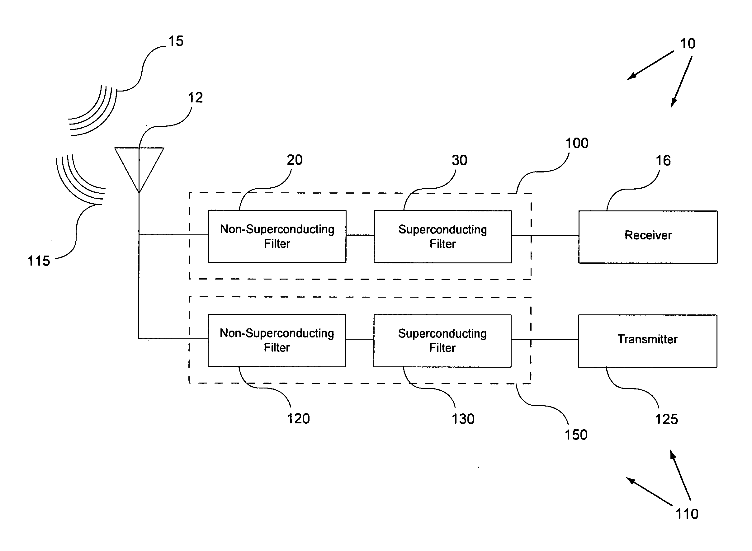
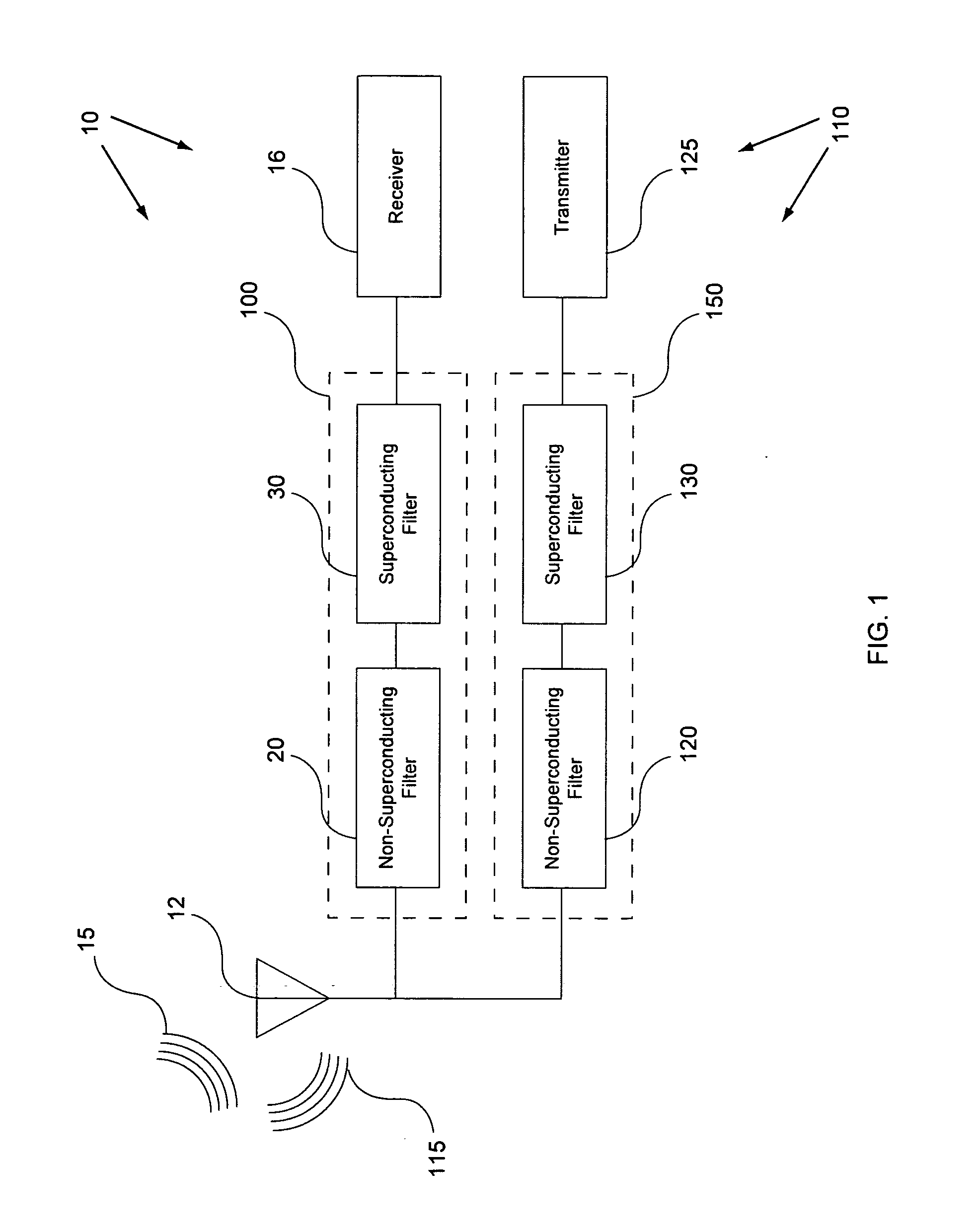
[0035] In general, the present invention is directed generally to providing systems and methods for designing an electronic communication system having improved signal filtering that may include, for example, one or more receiver(s), transmitter(s), and / or transceiver(s) having one or more signal amplifier(s) and / or signal filter(s). More particularly, the present invention is believed to be applicable to a variety of radio frequency (RF) applications in which achieving low insertion loss in the pass band with high attenuation in the stop band, and an extremely high degree of selectivity in the pass band are necessary. The present invention is particularly applicable and beneficial for cellular-communication base stations, and other communication applications. While the present invention is not so limited, an appreciation of the present invention is best presented by way of a particular example application, in this instance, in the context of such a communication system.

[0036] Now ...


PUM


Abstract

Systems and methods for communication system having improved transmitter and / or receiver performance. The invention may include systems and methods related to the use of non-superconducting and / or superconducting filters for a receiver and / or a transmitter. The invention is particularly useful in electronic communication systems that have heavy usage and requiring accurate and sharp channel filtering, for example wireless communication systems. In various embodiments, a receive filter network may include a non-superconducting filter and / or a superconducting filter. In various embodiments, a transmit filter network may include a non-superconducting filter and / or a superconducting filter. The superconducting filter(s) may be, for example, a band pass filter and / or a notch filter or band reject filter.

Description

CROSS-REFERENCE TO RELATED APPLICATIONS [0001] This application is a continuation-in-part of co-pending U.S. application Ser. No. 10 / 430,914, filed May 6, 2003, which is a continuation of co-pending U.S. application Ser. No. 09 / 818,100, filed Mar. 26, 2001, and now issued as U.S. Pat. No. 6,686,811, which are fully and expressly incorporated herein by reference.BACKGROUND OF THE INVENTION [0002] 1. Field of the Invention [0003] The present invention relates to the field of communications and, more specifically, to methods and systems for providing, at least in part, electronic communications. [0004] 2. Description of the Related Art [0005] Today there are numerous types of electronic or electronic assisted communication systems that include, for example, radio, television, cable, internet, two-way radio, cellular telephone systems, LANS, WANS, and optical communication systems. Many of these systems may employ various types of signal amplifiers and filters in their receivers and / or ...

Claims


Application Information

Patent Timeline
IPC IPC(8): H01P1/205H01P1/213
CPCH01P1/205H01P1/2136H01P1/2053
Inventor HEY-SHIPTON, GREGORY LYNTON
Owner SUPERCONDUCTOR TECHNOLOGIES INC
Why Eureka
Try Eureka