Side firing fiber optic array probe

a fiber optic array and probe technology, applied in the field of side firing fiber optic array probes, can solve the problems of high manufacturing or assembly costs of these conventional side-firing probes, poor adaptability to multi-fiber probes, and time-consuming, and achieve the effect of easy assembly and easy adjustment of separation

Inactive Publication Date: 2005-07-28
INFRAREDX INC
View PDF17 Cites 79 Cited by
  • Summary
  • Abstract
  • Description
  • Claims
  • Application Information

AI Technical Summary

Benefits of technology

[0019] An advantage of this embodiment is that it provides a non-astigmatic design and enables rigid alignment between the fibers, leveraging existing connector processes. Assembl

Problems solved by technology

The manufacture or assembly of these conventional side-firing probes is costly and a tim

Method used


Image

  • Side firing fiber optic array probe
  • Side firing fiber optic array probe
  • Side firing fiber optic array probe

Examples


first embodiment

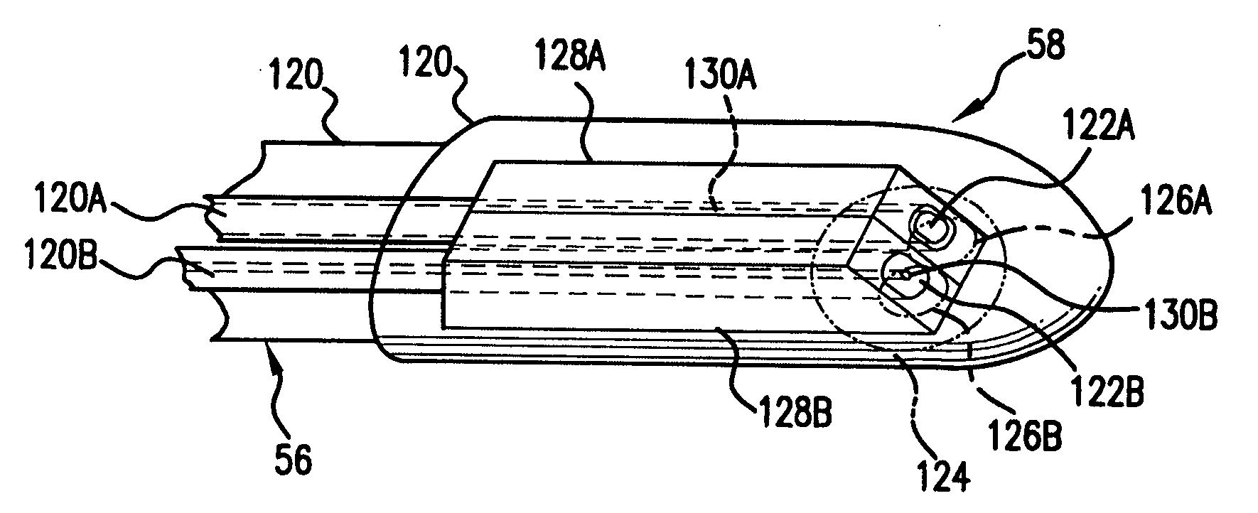
[0038] Multiple optical fibers extend through the catheter 56 to the catheter's head 58, within the casing 120. In this first embodiment, the two optical fibers 120A, 120B are provided. The terminal ends of these optical fibers 120A, 120B have side-firing terminations 122A, 122B. In one embodiment, these side-firing terminations 122A, 122B are coated to reflect light. In other examples, the index mismatch between the material of the optical fibers 120A, 120B and the medium adjacent to the side-firing terminations 122A, 122B, such as air, provides the required reflectivity. The side-firing terminations 122A, 122B, in effect, couple the optical fibers 120A, 120B to a region 124 that is lateral to the probe head 58.

[0039] Specifically, light emanating from the region 124 and directed radially with respect to an toward the fibers is reflected by the side-firing terminations 122A, 122B to be coupled into and propagated by the optical fibers 120A, 120B. Similarly, light propagating throug...

second embodiment

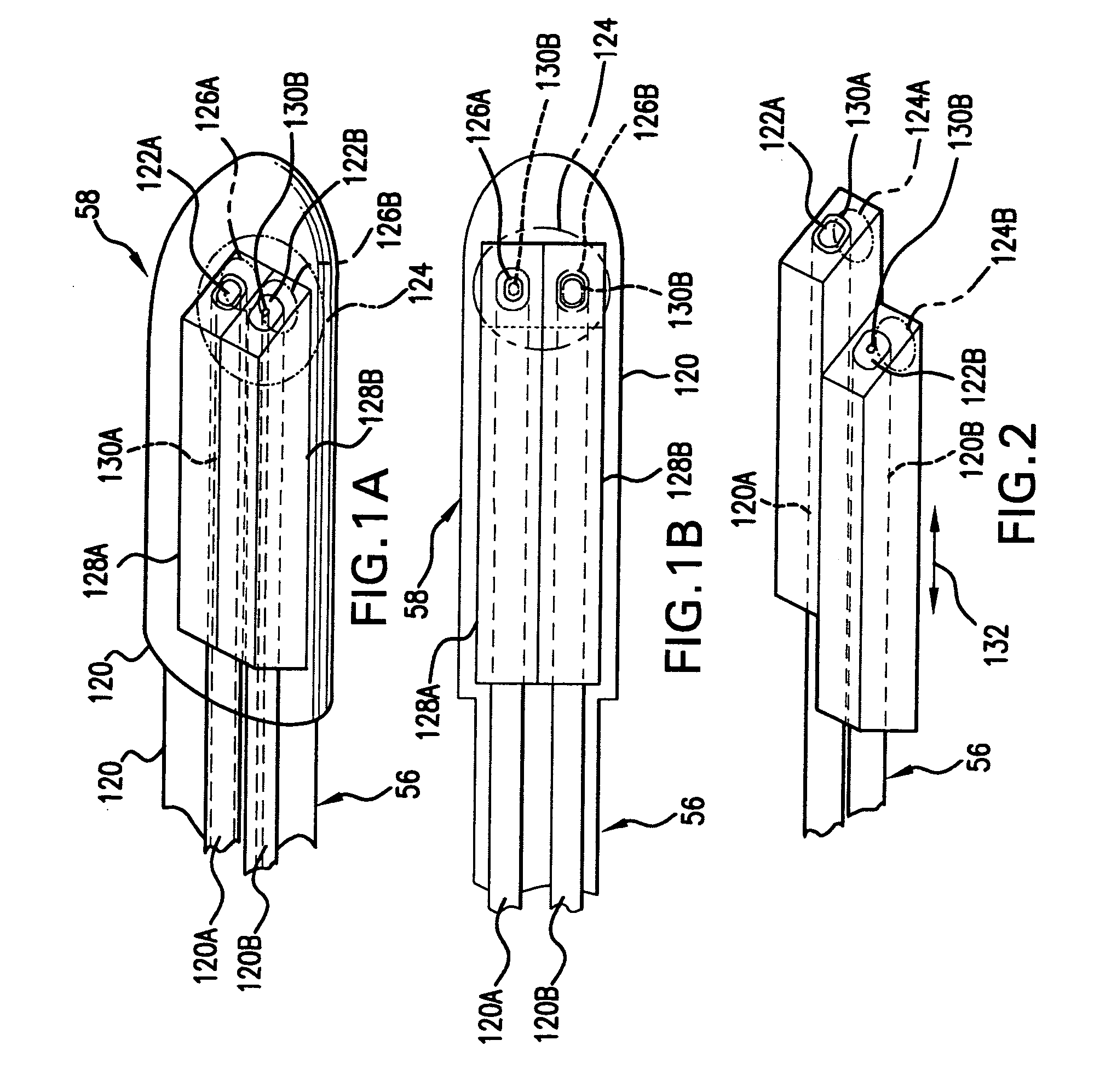
[0045]FIG. 2 shows the multi-fiber optic medical probe. In this example, the side-firing terminations 122A and 122B of optical fibers 120A and 120B, respectively, are longitudinally offset with respect to each other. The side-firing terminations are located at different positions along the longitudinal axis 132 of the catheter 56. As a result, the optical fiber 120A collects light from region 124A, whereas optical fiber 120B emits light into region 124B. This embodiment has the advantage of being able to control the position where the light is emitted and collected. It allows increases in the path length of light traveling from optical fiber 120B to 120A without substantially increases the width of the probe.

[0046] In the embodiments illustrated in FIGS. 1A, 1B, and 2, the manufacturing process for the multi-fiber optic medical probe is as follows. First, any coating or sheath on the optical fibers 120A, 120B is stripped. The optical fibers 120A, 120B are then slid or inserted into ...

third embodiment

[0051]FIG. 4 shows the multi-fiber optic medical probe. In this example, the four optical fibers 120A-128D are provided. Each has respective beam shaping apertures 126A-126D.

[0052] The advantage of the third embodiment is that multiple collection multimode optical fibers are provided. The multiple multi-mode fibers 126A, 126C, 126D are located at different longitudinal positions along the longitudinal axis 132 of the probe 56. This allows light emitted by the single mode optical fiber 120B to be collected at multiple distances by the multimode collection optical fibers 120A, 120C, 120D. This allows the spectral response to be collected from different pathlengths.


PUM


Abstract

A multi fiber optic medical probe comprises at least two optical fibers. There are side-firing terminations for the at least two optical fibers. Further, beam-shaping apertures are provided for controlling light propagating between the side-firing terminations and a region lateral to the probe. The provision of the at least two optical fibers allows for multiple optical signals to be transmitted to and/or from the target area within the patient. The side-firing terminations allow for the interrogation of regions that are adjacent to the probe, i.e., extending in a direction parallel to the insertion direction or longitudinal axis of the probe. The beam shaping apertures are provided for controlling light propagating between the side-firing terminations and the region lateral to the probe, in order to control the shape of the emitted beam and also, the direction from which light is collected.

Description

BACKGROUND OF THE INVENTION [0001] Probe-based, such as catheter-based, optical systems are applicable to a number of diagnostic and therapeutic medical applications. Optical coherence tomography is used to provide spatial resolution, enabling the imaging of internal structures. Spectroscopy is used to characterize the composition of structures, enabling the diagnosis of medical conditions by differentiating between cancerous, dysplastic, and normal tissue structures, for example. Ablation systems are used to remove or destroy structures within the body to address various diseases, such as tachycardias, tumors, and coronary artery disease, in another example of a probe-based optical system. [0002] For example, in one specific spectroscopic application, an optical source, such as a tunable laser, is used to access or scan a spectral band of interest, such as a scan band in the near infrared wavelengths or 750 nanometers (nm) to 2.5 micrometers (μm). The generated light is used to ill...

Claims


Application Information

Patent Timeline
IPC IPC(8): A61B5/00
CPCA61B1/00167A61B5/0084A61B5/0075
Inventor ZULUAGA, ANDRES F.KORN, JEFFREY A.
Owner INFRAREDX INC
Why Eureka
Try Eureka