
Autonomous vacuum cleaner

a vacuum cleaner and autonomous technology, applied in the direction of cleaning action control, process and machine control, instruments, etc., can solve the problem of not being able to accurately identify the material or type of the floor surface, and achieve the effect of accurate identification of the material of the floor surface and meticulous cleaning

Inactive Publication Date: 2005-08-04
FUNAI ELECTRIC CO LTD
View PDF0 Cites 240 Cited by
  • Summary
  • Abstract
  • Description
  • Claims
  • Application Information

AI Technical Summary

Benefits of technology

The present invention is an autonomous vacuum cleaner that can detect steps on a floor surface and identify the material of the floor surface using a line sensor. This allows for efficient cleaning and movement based on the floor surface condition. The cleaner includes a floor sensor, an obstacle detection sensor, a moving means, a light receiving sensor, and a floor surface distance calculating means. The moving means and cleaning means are controlled based on the distance distribution derived from the floor surface distance calculating means. The autonomous vacuum cleaner can also identify the material of the floor surface and protect it from damage by changing the cleaning conditions accordingly. The technical effects of the present invention include improved cleaning efficiency, stable movement, and accurate floor surface identification.

Problems solved by technology

Thus there still exists a problem that it is not possible to accurately identify the material or kind of the floor surface.

Method used


Image

  • Autonomous vacuum cleaner
  • Autonomous vacuum cleaner
  • Autonomous vacuum cleaner

Examples


Embodiment Construction

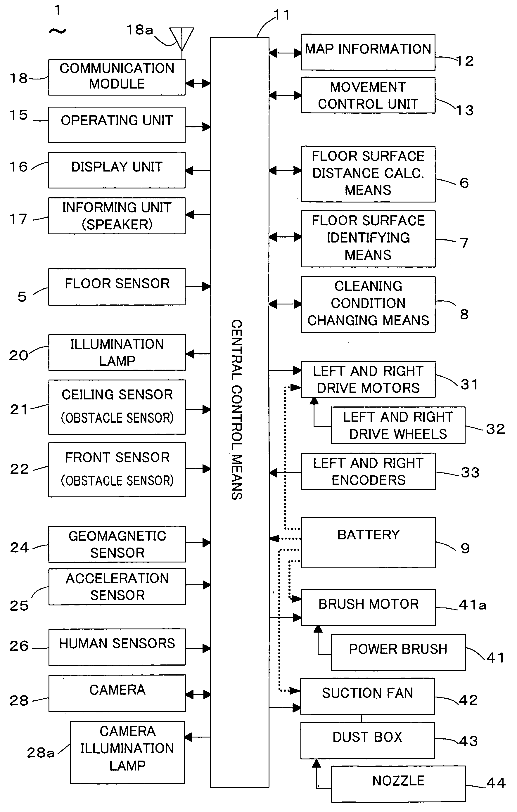
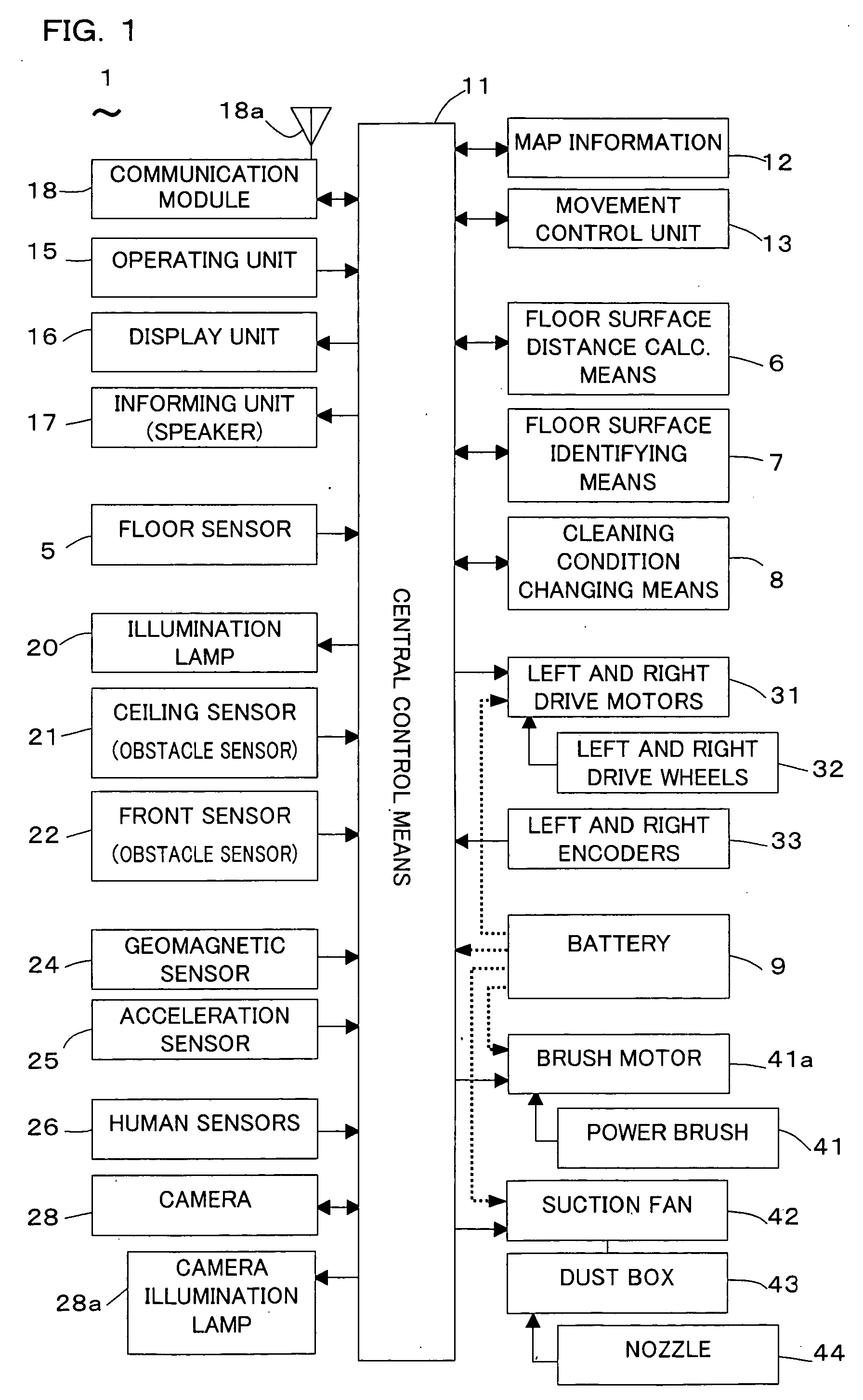
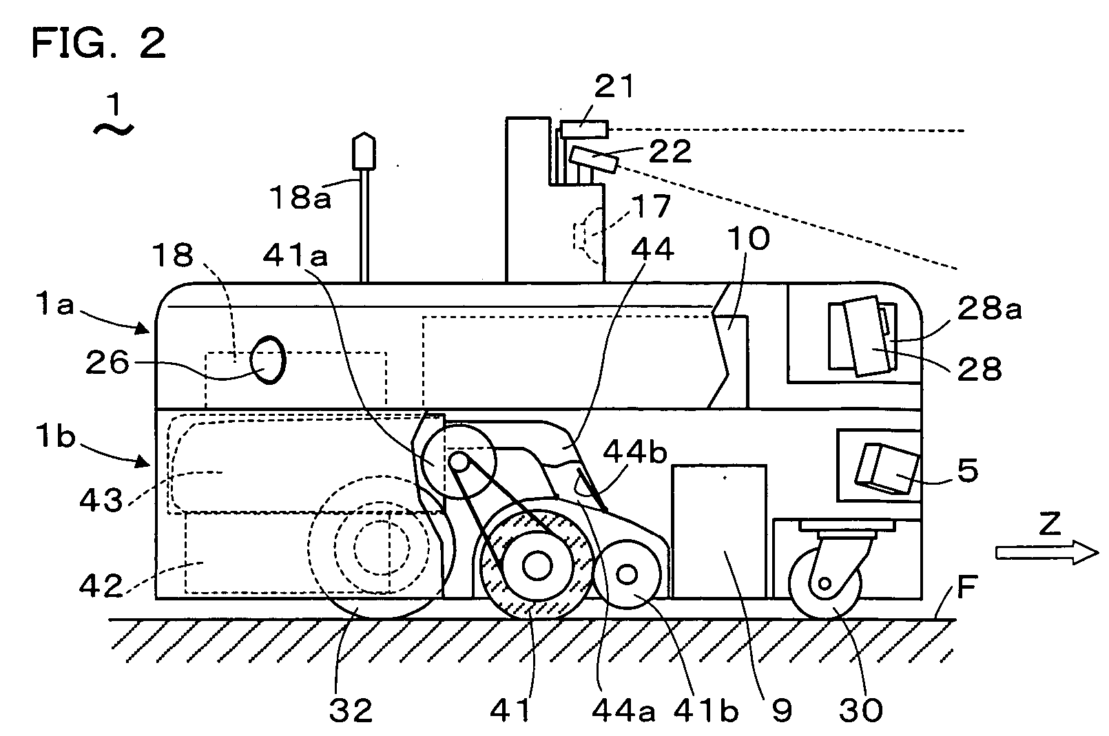
[0041] An autonomous vacuum cleaner according to an embodiment of the present invention will be described hereinafter with reference to the annexed drawings. FIG. 1 shows an electrical block diagram of an autonomous vacuum cleaner 1 according to the present embodiment. FIG. 2 shows a partially cutaway side view of the autonomous vacuum cleaner 1. FIG. 3A and FIG. 3B show an upper part and a lower part of the autonomous vacuum cleaner 1, respectively, as separated.

[0042] As shown in FIG. 3A and FIG. 3B, the autonomous vacuum cleaner 1 is a three-wheeled vehicle having an outer shape formed of two disk-shaped parts, namely a cleaner-upper-part 1a and a cleaner-lower-part 1b, stacked vertically on each other. The cleaner-upper-part 1a comprises mainly various sensors and control devices, while the cleaner-lower-part 1b comprises a moving means and a cleaning means. In the following, the autonomous vacuum cleaner 1 will be described by referring mainly to the electrical block diagram o...


PUM


Abstract

An autonomous vacuum cleaner comprises: obstacle detection sensors; moving means; a cleaning means including a power brush, a suction fan and a nozzle for sucking up dust on a floor surface; floor surface sensors each comprising a passive-type CMOS line sensor to receive light from the floor surface for detecting floor surface conditions. It performs cleaning while autonomously moving. Based on received light signals of the floor surface sensors, distance distributions to floor surface areas within the viewing angle of each sensor are derived. Detection of a step on the floor surface and identification of the material of the floor surface (polished floorboard, tatami or carpet) are performed by analyzing spatial frequency in the distance distribution. Based on the identification, cleaning conditions including at least the moving speed, the dust suction force of the suction fan or the brushing strength of the power brush are changed. With simple structure using one same floor sensor, this autonomous vacuum cleaner can detect a step on a floor surface and can more accurately identify the material of the floor surface, thereby enabling meticulous cleaning.

Description

BACKGROUND OF THE INVENTION [0001] 1. Field of the Invention [0002] The present invention relates to an autonomous vacuum cleaner. [0003] 2. Description of the Related Art [0004] In a conventional autonomous vacuum cleaner for cleaning a floor surface, floor sensors are used to check the floor surface where the vacuum cleaner moves around and sweeps. For example, such a floor sensor is known which comprises an ultrasonic sensor transmitting an ultrasonic signal to the floor surface and receiving the ultrasonic signal reflected from the floor surface, which is used in a manner that the ultrasonic signal reciprocating between the ultrasonic sensor and the floor surface plural times is integrated by an integrating circuit, and the level of the integrated signal is determined to identify the kind of the floor surface, and to control the operation of a power brush dedicated to carpet cleaning (refer to e.g. Japanese Patent No. 2820407). [0005] Further, a floor sensor is known which compr...

Claims


Application Information

Patent Timeline
Patent Type & Authority Applications(United States)
IPC IPC(8): A47L9/28A47L5/00G05D1/02
CPCG05D1/0246G05D1/0255G05D1/0259G05D1/027G05D1/0274A47L9/2805A47L9/2826A47L9/2842A47L9/2847A47L9/2852A47L9/2894A47L2201/04A47L2201/06
Inventor UEHIGASHI, NAOYA
Owner FUNAI ELECTRIC CO LTD
Learn More