Resonator adopting counter-bored holes and method of suppressing combustion instabilities

Active Publication Date: 2005-08-04
SIEMENS ENERGY INC
View PDF12 Cites 37 Cited by
  • Summary
  • Abstract
  • Description
  • Claims
  • Application Information

AI Technical Summary

Benefits of technology

[0008] The present invention provides a through-flow resonator, which when placed at or near the points having the highest acoustical pressure amplitudes within the flow path of a combustor system, effectively dampens

Problems solved by technology

Because the acoustic inertance of a plain cylindrical hole, such as those commonly found in the downstream hole patterns of system resonators, is directly proportiona

Method used


Image

  • Resonator adopting counter-bored holes and method of suppressing combustion instabilities
  • Resonator adopting counter-bored holes and method of suppressing combustion instabilities
  • Resonator adopting counter-bored holes and method of suppressing combustion instabilities

Examples


Embodiment Construction

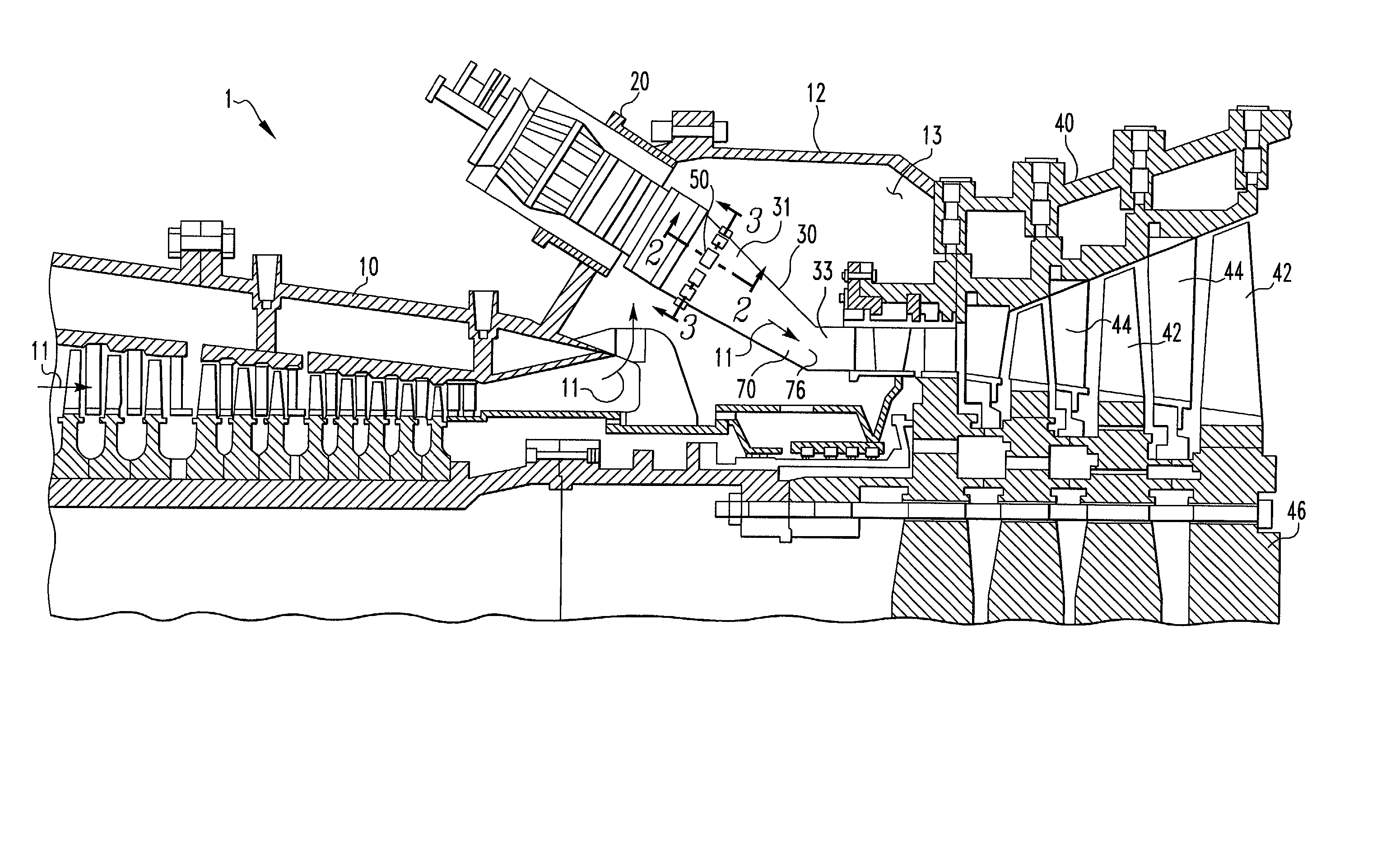
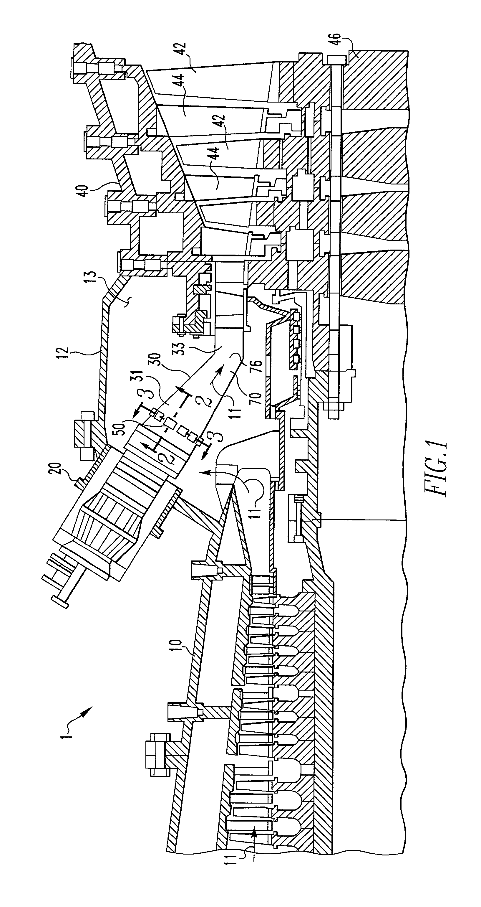
[0024] As shown in FIG. 1, a combustion turbine power plant 1 includes a compressor assembly 10, a combustor assembly 20, a transition section 30, and a turbine assembly 40. The compressor assembly 10, combustor assembly 20, transition section 30, and turbine assembly 40, define a flow path 11. The combustor assembly 20 may be a can-annular or annular combustor assembly.

[0025] As is known in the prior art, the compressor assembly 10 includes a plurality of rotating blades and stationary vanes structured to compress a fluid. The combustor assembly 20 is disposed within a casing 12. The casing 12 defines a plenum 13. Compressed air from the compressor assembly 10 is delivered to the plenum 13. The combustor assembly 20 is coupled to a fuel source (not shown). Within the combustor assembly 20, compressed air and fuel are mixed, ignited and consumed in a combustion zone, thereby creating a working gas. The working gas is delivered through flow path 11 within the transition section 30. ...


PUM


Abstract

A resonator for damping pressure waves or instabilities in a system supported by acoustic energy wherein the resonator adopts the use of counter-bored openings on the downstream side of the resonator within the flow path of the system. The resonator includes a first member and a second member where the second member includes a plurality of openings therethrough with each hole having a counter-bore on its upstream side. The first member has a size substantially smaller than the diameter of said flow path and a first plurality of openings therethrough. The openings are in fluid communication with the flow path. The second member has a size generally equal to the first member and a second plurality of openings therethrough, which openings are in fluid communication with the flow path.

Description

[0001] This application is a continuation-in-part of the application having application Ser. No. 09 / 667409 filed on Sep. 21, 2000, which is specifically incorporated herein by reference.BACKGROUND OF THE INVENTION [0002] This invention relates in general to a resonator for damping pressure waves or instabilities supported by acoustic energy within a system and, more specifically, to the use of counter-bored holes to increase the acoustic conductance of a resonator within a system having a combustor. The resonator may be placed at or near the location within the system having the highest acoustic pressure amplitude. This invention also relates to a method of placing a resonator adopting counter-bored holes at or near the locations of the highest acoustic pressure amplitudes within a system to suppress combustion instabilities so that the mass flow of air bypassing the system's combustor is maintained within design tolerances. [0003] One common type of device used for damping the effe...

Claims


Application Information

Patent Timeline
IPC IPC(8): F23M20/00F23R3/16F23R3/00F23R3/42
CPCF01D25/30F02C7/24F23D2210/00F23M20/005F23R2900/00014F05D2260/96F23R3/002F23R3/00
Inventor SATTINGER, STANLEY S.
Owner SIEMENS ENERGY INC
Why Eureka
Try Eureka