Apparatus and methods for preventing rotational slippage between a vertical shaft and a support structure for a semiconductor wafer holder

a technology of vertical shaft and support structure, which is applied in the direction of coating, metallic material coating process, chemical vapor deposition coating, etc., can solve the problems of shaft and spider socket not being precisely aligned, surface slippage with respect to one another, and deformation of mating surfaces, etc., to prevent rotational slippage, prevent rotational slippage of susceptor holder, prevent the effect of rotational slippage of the substrate holder suppor

Active Publication Date: 2005-08-04
ASM IP HLDG BV
View PDF12 Cites 5 Cited by
  • Summary
  • Abstract
  • Description
  • Claims
  • Application Information

AI Technical Summary

Benefits of technology

[0011] In accordance with another aspect of the present invention, a method of assembling a rotating susceptor assembly for a semiconductor processing system is provided. A substrate holding structure is coupled to a rotational linkage so as to prevent rotational slippage of the susceptor holding structure relative to the rotational linkage during rotation of the substrate holding structure.
[0012] In accordance with another aspect of the present invention, a method of rotating a substrate is provided. A susceptor assembly is rotated by coupling a substrate holding assembly to a rotational linkage so as to prevent rotational slippage of the susceptor holder support relative to the a rotational source when the substrate holding assembly is rot

Problems solved by technology

Slippage between a spider socket and the rotation shaft causes polishing of the precisely machined mating surfaces of the shaft and the socket interior, thereby deforming the mating surfaces so that the shaft and the spider socket no longer precisely fit together.
This polishing of the machined surfaces of the shaft and socket inter

Method used


Image

  • Apparatus and methods for preventing rotational slippage between a vertical shaft and a support structure for a semiconductor wafer holder
  • Apparatus and methods for preventing rotational slippage between a vertical shaft and a support structure for a semiconductor wafer holder
  • Apparatus and methods for preventing rotational slippage between a vertical shaft and a support structure for a semiconductor wafer holder

Examples


Embodiment Construction

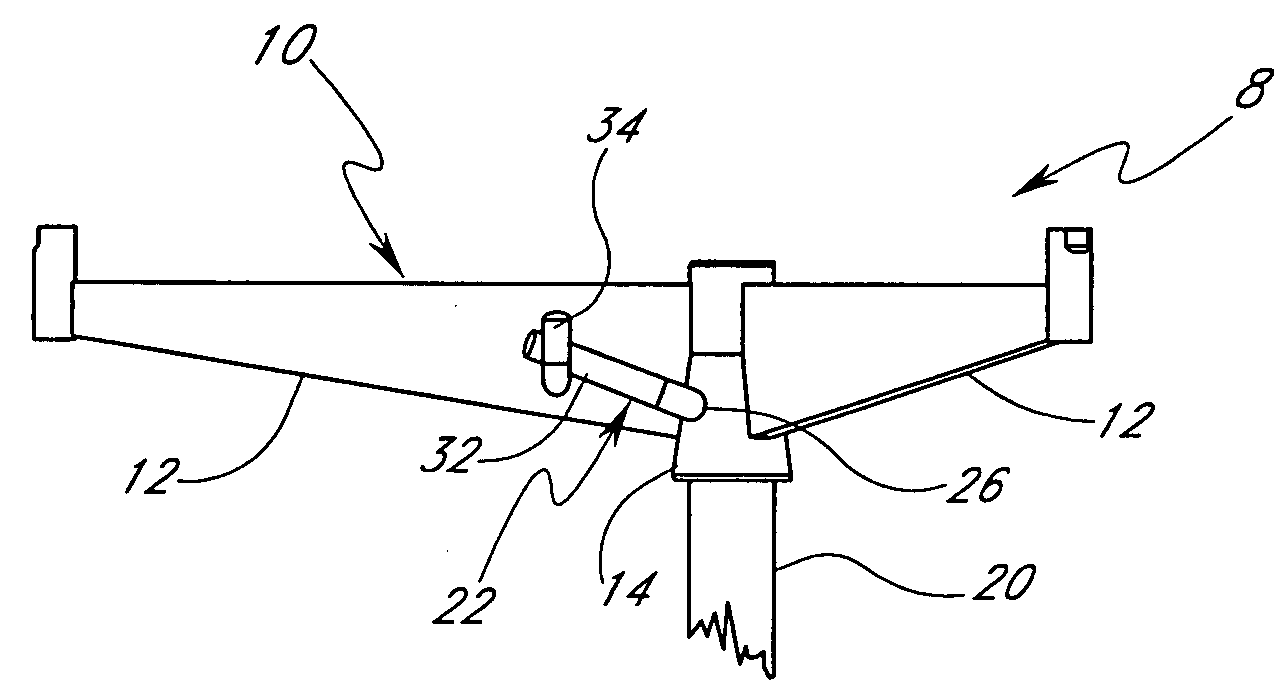
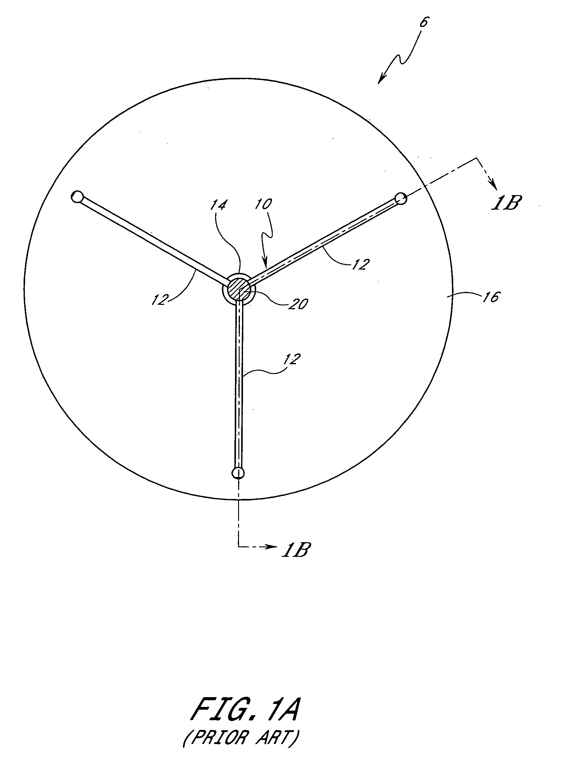
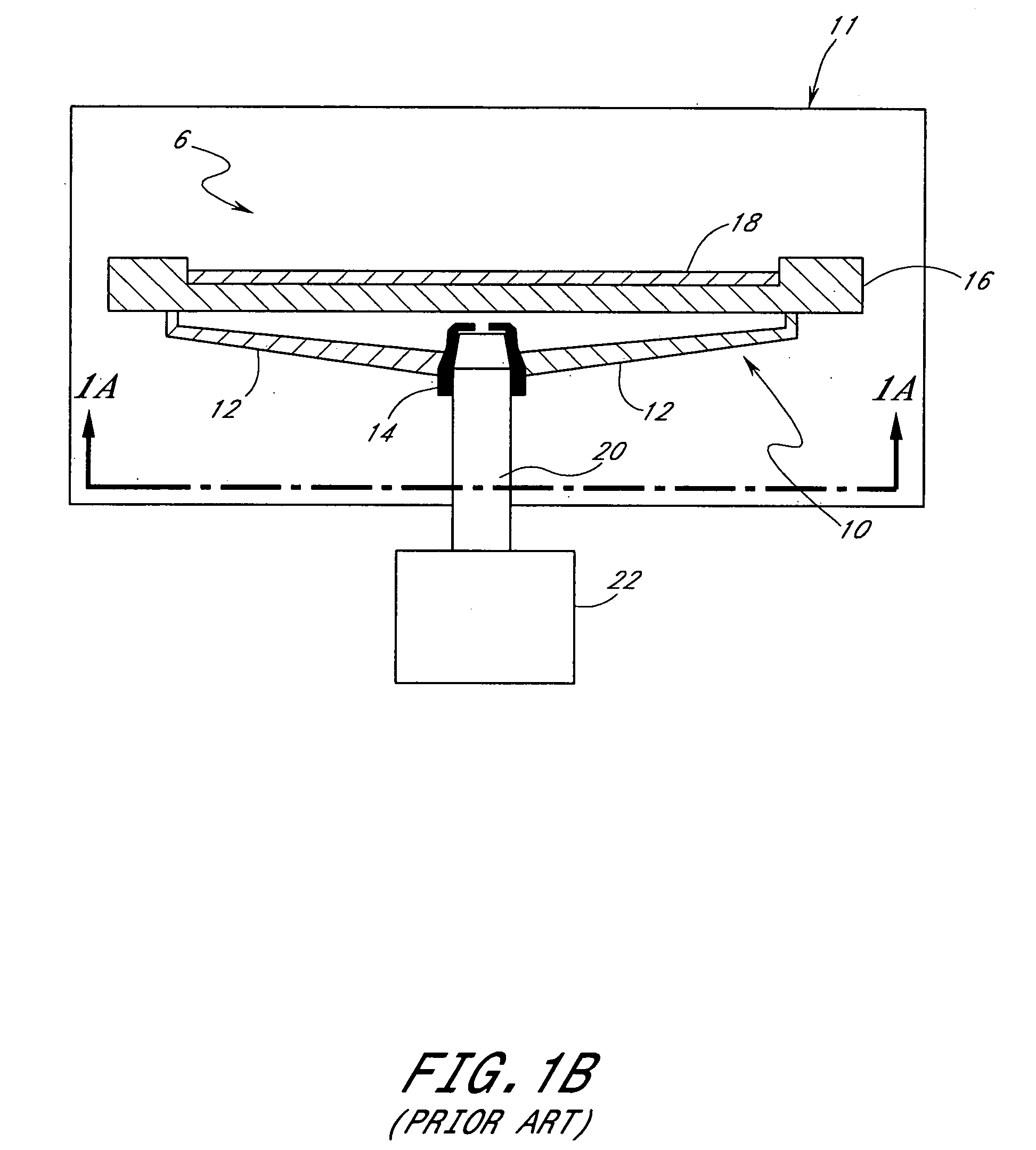
[0041]FIGS. 1A and 1B are schematic depictions of a support assembly 6 of the prior art. A substrate (or wafer) holder support, or spider 10, is shown in a reaction chamber 11. The spider 10 has a plurality of support arms 12 extending radially outward and upward from a central socket 14 to support the underside of a substrate holder 16, such as a susceptor. The substrate holder 16 rests upon the support arms 12 and is configured to hold a substrate or wafer 18. Underneath the spider 10, an elongated shaft 20 is mated with the spider socket 14, providing a coupling that allows the spider 10 to be rotated when the elongated shaft 20 is rotated by a motor 22. As explained above in the Background section, this coupling does not satisfactorily prevent relative rotation between the shaft 20 and the socket14, particularly when the mass of the system has increased by movement from 200 mm wafers to 300 mm wafers. Also, as the mating surfaces rub against one another and deform, wobbling of t...


PUM

PropertyMeasurementUnit
Lengthaaaaaaaaaa
Lengthaaaaaaaaaa
Forceaaaaaaaaaa

Abstract

A substrate support assembly positively secures a substrate holder support to a rotation shaft with respect to rotationally applied forces. A substrate holder support is configured to have an opening in a socket into which, when aligned with an indentation in the rotational shaft to form a passage, a retaining member is removably inserted to engage both the socket opening and the shaft indentation. Methods of rotating a substrate while minimizing rotational slippage of the substrate holder support with respect to the shaft are also provided.

Description

BACKGROUND OF THE INVENTION [0001] 1. Field of the Invention [0002] The present invention generally relates to the field of substrate processing and, more particularly, to apparatuses and methods for preventing relative rotation of a vertical support shaft and a support structure for a wafer holder. [0003] 2. Description of the Related Art [0004] In the processing of substrates, such as semiconductor wafers, a substrate or wafer holder is generally employed inside a reaction chamber to both evenly support a wafer and to ensure even heat distribution across the surface of the wafer. If the wafer holder helps to attract radiant energy, it is called a susceptor. The susceptor or wafer holder is supported by an underlying support (e.g., a quartz “spider”) having a socket which is configured to mate with a portion of an elongated rotation shaft. In one common configuration, the shaft is rotationally linked to a motor, which effectuates the rotation of the support. In turn, the wafer hold...

Claims


Application Information

Patent Timeline
IPC IPC(8): H01L21/683C23C16/00C23C16/458H01L21/68H01L21/687
CPCC23C16/4584Y10T29/41H01L21/68792H01L21/68728H01L21/68
Inventor WEEKS, THOMAS M.BARNETT, LEWIS C.JACOBS, LOREN R.WOOD, ERIC R.HALPIN, MICHAEL W.
Owner ASM IP HLDG BV
Why Eureka
Try Eureka