Microengineered optical scanner

a micro-engineered, optical scanner technology, applied in the direction of optics, optical light guides, electromagnetic radiation sensing, etc., can solve the problems of not being able to meet the needs of moving source systems, lack of appropriate signal detection, and inability to read true systems, so as to reduce the noise of un-wanted noise, reduce the noise, and increase the range of operation of the device

Inactive Publication Date: 2005-08-04
MICROSAIC SYST
View PDF11 Cites 36 Cited by
  • Summary
  • Abstract
  • Description
  • Claims
  • Application Information

AI Technical Summary

Benefits of technology

[0041] This is advantageous in reducing the pick up of un-wanted noise, with the effect that the lower the noise the greater the range of operation of the device.
[0042] The motion sensors are typically placed near the root of the cold arm and the root of the cantilever. This assists in maintaining the known scan amplitude which may otherwise be difficult to monitor. These may be constructed as piezo-resistive or capacitative devices or some other suitable type detector.

Problems solved by technology

It is harder to satisfy in a moving source system.
However, the vast majority lack any appropriate signal detection, and are therefore not true reading systems.
The most complicated MEMS moving mirror scanners have used surface micro-machining methods to create sets of flat parts.
MEMS-based moving source scanners have received less attention, because of the difficulty of constructing a suitable confocal detection system.
However, it results in a low detected signal, because only a small fraction of the available back-scattered light is collected.
The useful range of a bar code reader constructed in this way is therefore small.
However it was also shown that the magnification of the lens has a significant effect on performance and that the requirements on magnification for detection and scanning are therefore in conflict.
Constrained thermal expansion results in an axial force, which buckles the beam laterally when the first Euler critical load is reached.
Despite these advances, little progress has been made in developing an integrated pre-objective scanner.

Method used


Image

  • Microengineered optical scanner
  • Microengineered optical scanner
  • Microengineered optical scanner

Examples


Embodiment Construction

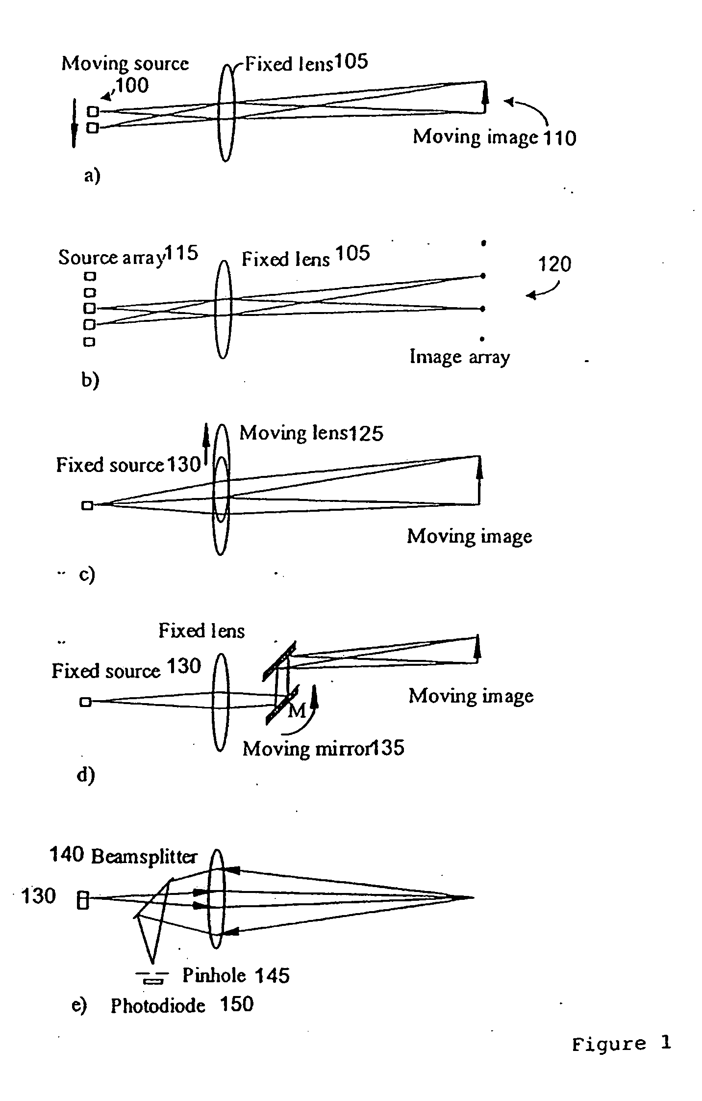
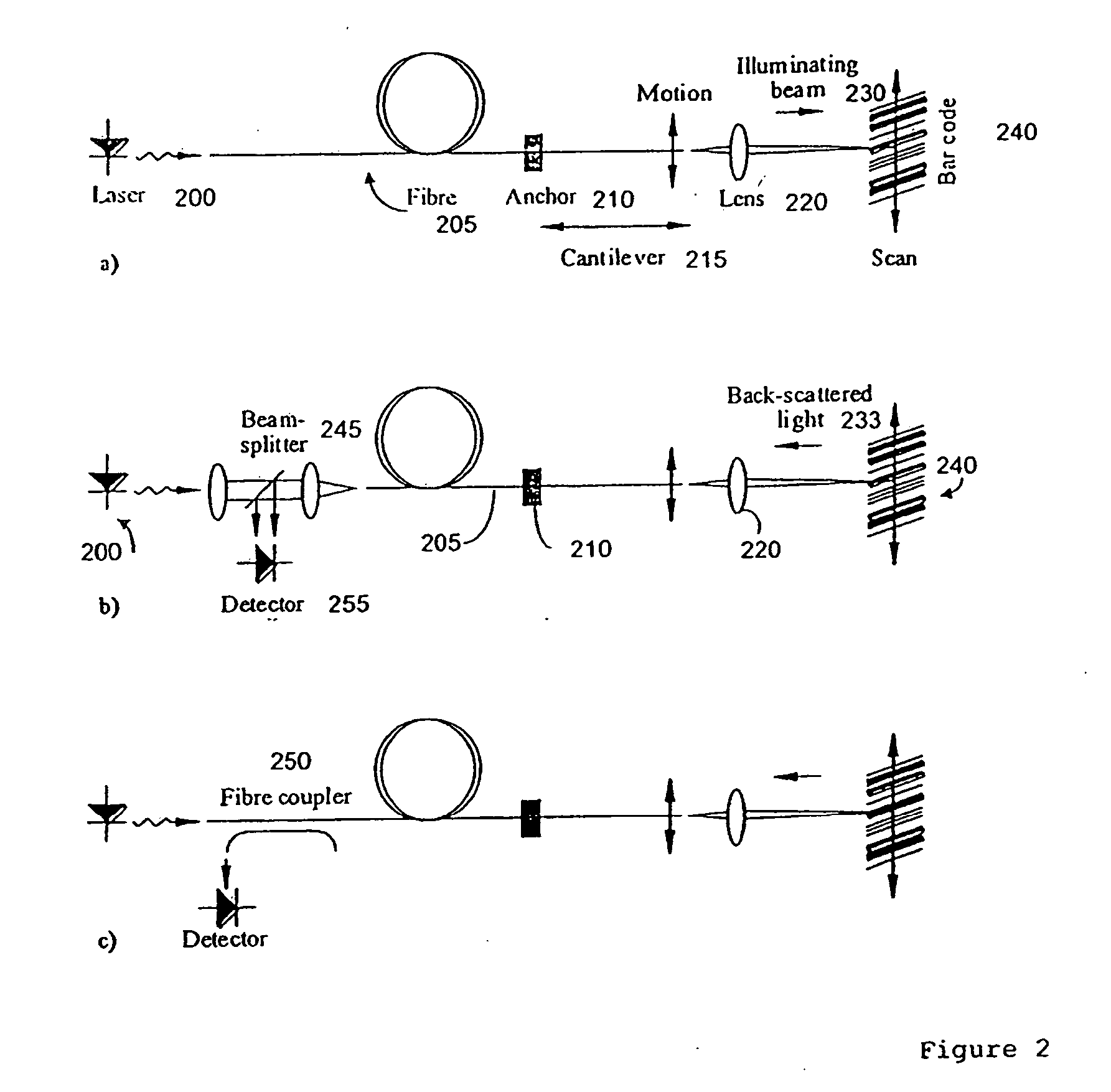
[0090] FIGS. 1 to 5 have been described previously with reference to prior art implementations.

[0091] The present invention will now be described with reference to FIGS. 6 to 14.

[0092]FIG. 6 shows an integrated optical reader according to the present invention. The optical detection device provides an actuator (640) for effecting movement of a optical waveguide (630) and a detector (635) for detecting the light, which is predominately backscattered light. Both are integrally formed in a substrate (605). In a preferred embodiment a movement of the waveguide is provided by coupling the waveguide to a cantilever and actuating the cantilever to effect an associated movement of the waveguide. Desirably the detector is adapted to detect the cladding mode components of a waveguide. Preferably these components of the optical detection device are combined with a light source, a waveguide and motion detectors.

[0093] We now give a detailed description of the invention, considering in turn a...


PUM


Abstract

A microengineered optical scanner based on a moving cantilevered dielectric waveguide is described. The waveguide is excited into resonant mechanical motion by a drive located at its root. Stress sensors detect the bending of the waveguide, allowing closed loop control of the motion. A moving image of the light emitted from the moving tip of the waveguide is created by a lens. The moving image acts as a scan line. Light back-scattered from a rough surface placed at the image plane is collected back into the waveguide by confocal imaging. The light collected in the cladding of the waveguide has higher numerical aperture than the light collected in the core. The cladding light is detected by a mode-stripping detector. Techniques for combining a cantilevered waveguide, a drive, motion sensors and a mode-stripping detector using microelectromechanical systems (MEMS) technology are described.

Description

FIELD OF THE INVENTION [0001] The invention relates to optical scanners and in particular to a microengineered optical scanner or optical reading device and methods for making such a device. BACKGROUND [0002] Bar code readers and scanners are optical information gathering systems. They operate by sweeping a point image through a set of trajectories and using confocal detection to collect light back-scattered from objects present in the focal plane. In a point-of-sales (POS) application, the object is a coded bar pattern, which provides brand and category information on an item to be sold. Other applications include inventory control and video programming. In many of these applications, it is important that the scanners be portable and lightweight, and allow hands-free operation. There is therefore a strong incentive to reduce their size and cost. [0003] There are several methods of generating the scan line in a bar code reader. A static point image may be created, simply by using a ...

Claims


Application Information

Patent Timeline
Patent Type & Authority Applications(United States)
IPC IPC(8): G02B6/35G06K7/10
CPCG02B6/3502G02B6/3566G06K7/10653G02B6/358G02B6/3584G02B6/3576
Inventor SYMS, RICHARDHOLMES, ANDREW
Owner MICROSAIC SYST
Why Eureka
Try Eureka