Flash lamp with high irradiance

a flash lamp and high irradiance technology, applied in the field of flash lamps, can solve the problems of high temperature state, excessive wall load of discharge vessels, premature deterioration of electrodes, etc., and achieve the effect of long service life and high radiation intensity

Inactive Publication Date: 2005-08-04
USHIO DENKI KK
View PDF3 Cites 12 Cited by
  • Summary
  • Abstract
  • Description
  • Claims
  • Application Information

AI Technical Summary

Benefits of technology

[0014] A primary object of the present invention is to devise a flash lamp with high ra

Problems solved by technology

In a flash lamp which emits such radiation with a high radiance, however, the following disadvantages have increasingly appeared: Since emission takes place in a state with a high current density, a high temperature state is caused.
In this way, deterioration of the electrodes occurs prematurely.
The discharge vessel is subject to an enormous wall load.
This causes premature deterioration of the discharge vessel.
This prematur

Method used


Image

  • Flash lamp with high irradiance
  • Flash lamp with high irradiance
  • Flash lamp with high irradiance

Examples


embodiment 1

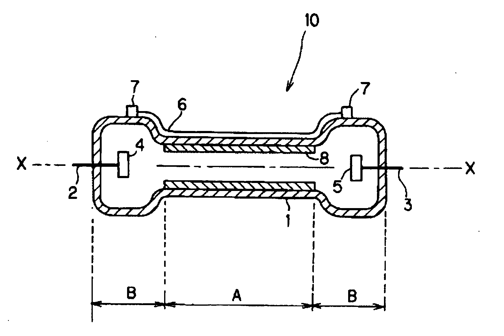
[0066] It is advantageous to reduce the inside diameter of the area of the discharge vessel in which the discharge takes place in order to increase the current density. FIG. 1 shows one example of a specific arrangement of this lamp.

[0067] A flash lamp 10 has a discharge vessel 1 which is present between the electrodes 4, 5 and which comprises a part A with a reduced inside diameter. The two ends B of the discharge vessel 1 are areas which are provided with electrodes and have a relatively great inside diameter. Consequently, the entire discharge vessel 1, in this example, is formed essentially in the form of a hand weight. Since, generally, a round tube is used for the discharge vessel 1, the middle of the part A with the small diameter, of the tube and of the two ends B on the tube axis X-X, and their cross sections are round. The cross-sectional shape, however, is not always limited to a circular shape. From the two ends of the discharge vessel 1, there extend electrode rods 2, ...

embodiment 2

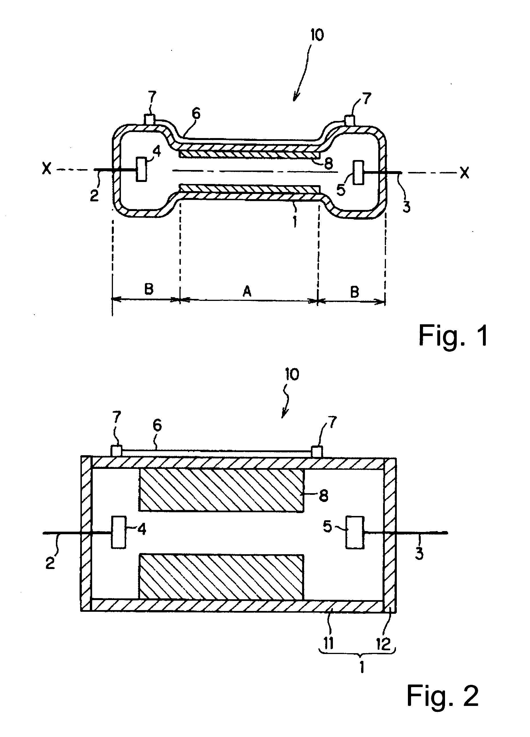
[0069] In order to be able to place the part with a small diameter in the discharge vessel, the arrangement shown in FIG. 2 can also be undertaken. Here, another tubular component 8 is slipped onto the inside of the tube 11 of the discharge vessel and attached; its outside diameter is equal to the inside diameter of the tube. On the two ends of the tube 11, there is a cover 12 so that, overall, a cylindrical discharge vessel 1 is formed. In this case, the tube 8 must have a certain thickness on the inside in order to constrict the discharge part. The arrangement of the electrodes 4, 5 is identical to FIG. 1.

embodiment 3

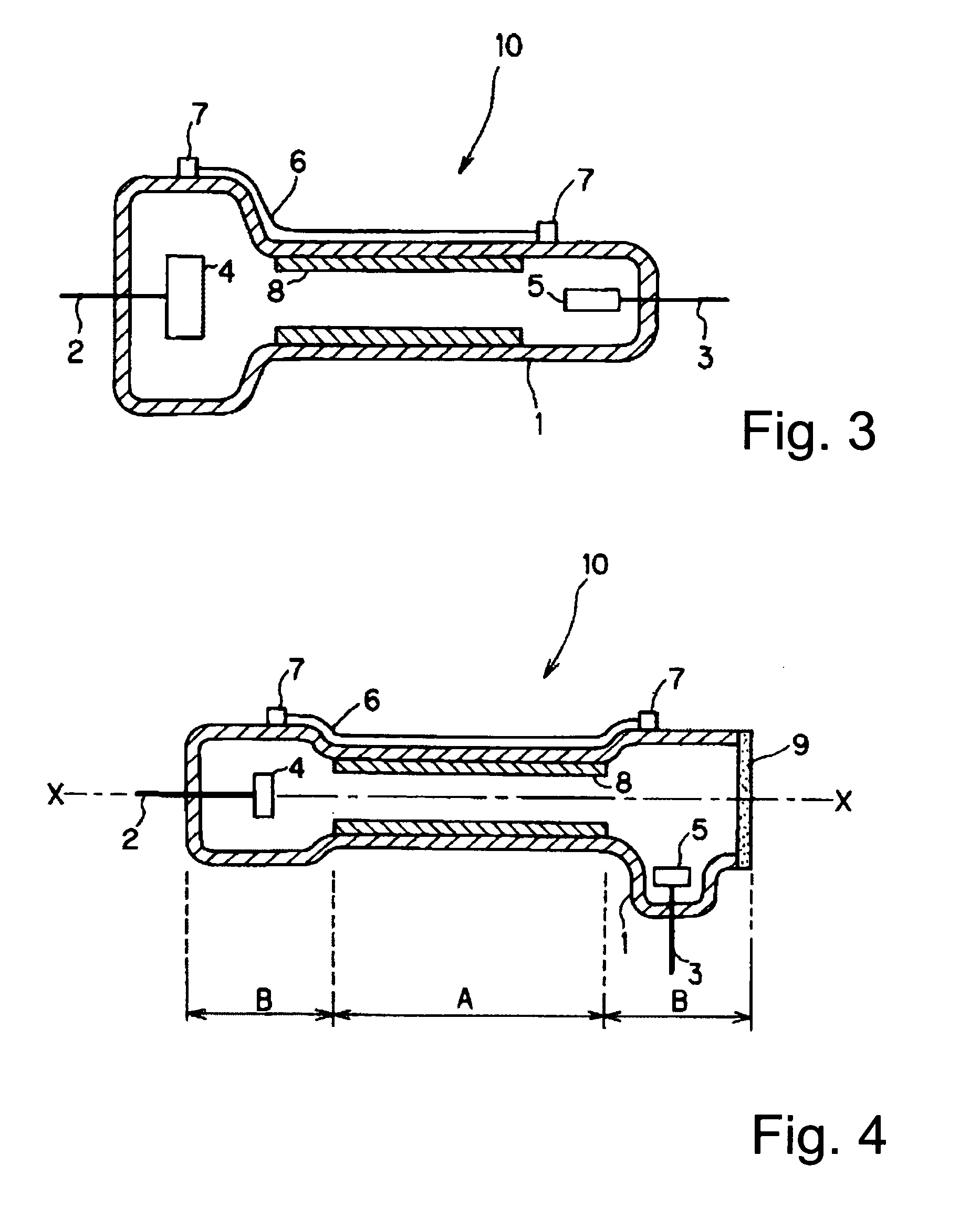
[0070] In the above described two examples, the electrode size of the anode 5 is essentially identical to the size of the cathode 4. However, this need not always be the case. It is disadvantageous for the cathode in which sputtering often takes place as a result of ion collision to be made small. However, the anode for which this disadvantage is minor can be made as a relatively small electrode. Therefore, as shown in FIG. 3, the diameter of the cathode 4 and the inside diameter of the discharge vessel 1 which surrounds the cathode 4, and thus, the cathode 4, can be made larger and also an arrangement of the discharge vessel 1 can be undertaken in which not only the inside diameter of the middle of the discharge vessel, but also the inside diameter of the discharge vessel area surrounding the anode 5, can be reduced.

[0071] In the embodiments 1 to 3 of FIGS. 1 to 3, there is a trigger electrode 6 running along the outside of the discharge vessel 1. A stop 7 for the trigger electrod...


PUM


Abstract

A flash lamp with high radiation intensity which has a discharge vessel having a part in the region between the electrodes which has a smaller diameter than the inside diameter of the discharge vessel in the area in which the cathode is located, and the inner surface of the part of smaller diameter being provided with a heat-resistant material. A xenon gas is filled into the vessel at a room temperature pressure from 1.3×10³ Pa to 1.6×10⁵ Pa or a krypton gas is filled at 7×10² Pa to 1.3×10⁵ Pa. A power supply operates the flash lamp with a full width at half maximum of the current from 150 μs to 2 ms and a current density in the part with a small diameter of at least 2110 A/cm2 when xenon is used and at least 2930 A/cm2 when krypton is used.

Description

BACKGROUND OF THE INVENTION [0001] 1. Field of the Invention [0002] The invention relates to a flash lamp filled with a rare gas such as xenon (Xe), krypton (Kr) and the like for emission. The invention relates especially to a flash lamp with high radiation density which is advantageously used for sterilization, curing of a photosensitive curing resin by UV radiation or visible radiation and for similar purposes. [0003] 2. Description of the Prior Art [0004] Recently, a sterilization method using a flash lamp has been used because a flash lamp has the advantage that, by two mechanisms, specifically a photochemical mechanism which is used for sterilization by UV-C and UV-B radiation, and a photothermodynamic mechanism which is used to generate heat, a sterilization effect can be obtained. A flash lamp for sterilization purposes is described, for example, in Japanese patent disclosure document JP-A-2001-185088. [0005] In order to increase the sterilization effect by the photochemical ...

Claims


Application Information

Patent Timeline
IPC IPC(8): H05B41/32A61L2/10H01J5/04H01J61/16H01J61/30H01J61/54H01J61/72H01J61/88H01J61/90H05B41/30
CPCA61L2/10H01J61/16H01J61/302H05B41/30H01J61/88H01J61/90H01J61/547
Inventor HIRAMOTO, TATUMIMORIMOTO, YUKIHIROMORI, KAZUYUKITORIKAI, TETUYA
Owner USHIO DENKI KK
Why Eureka
Try Eureka