System for automatically generating continuous developed still image from video image of inner wall of tubular object

Inactive Publication Date: 2005-08-04
AKIZUKI NAOMICHI +2
View PDF5 Cites 27 Cited by
  • Summary
  • Abstract
  • Description
  • Claims
  • Application Information

AI Technical Summary

Benefits of technology

[0022] As described above, with the system for automatically generating the continuous developed still image from the video image of the inner wall of the tubular object according to the present invention, since the movement quantity or direction of the image can be obtained by calculation based on the image data, thereby making it unnecessary to acquire the attitude information of the camera, so as to dispense with a special camera, unlike in the prior art. Furthermore, since the width of the strip to be cut is adjusted according to the movement quantity, it becomes unnecessary to move the camera at a constant speed at the time of photographing, thereby making it unnecessary to use a special photographing technique or provide a special p

Problems solved by technology

Furthermore, since the width of the strip to be cut is adjusted according to the movement quantity, it becomes unnecessary to move the camera at a constant speed at the time of photograph

Method used


Image

  • System for automatically generating continuous developed still image from video image of inner wall of tubular object
  • System for automatically generating continuous developed still image from video image of inner wall of tubular object
  • System for automatically generating continuous developed still image from video image of inner wall of tubular object

Examples


Example

[0033] A preferred embodiment according to the present invention will be described below with reference to the accompanying drawings.

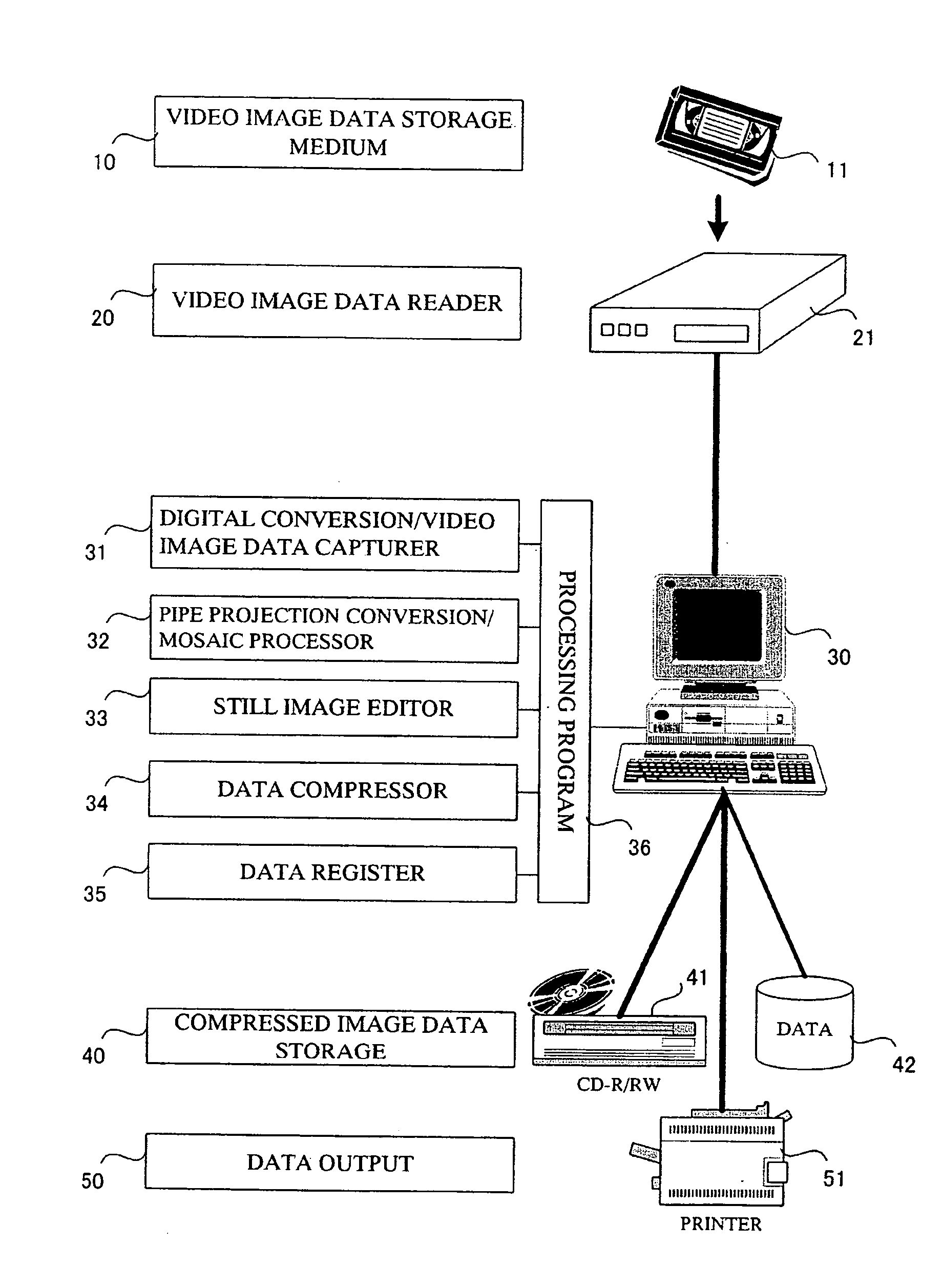
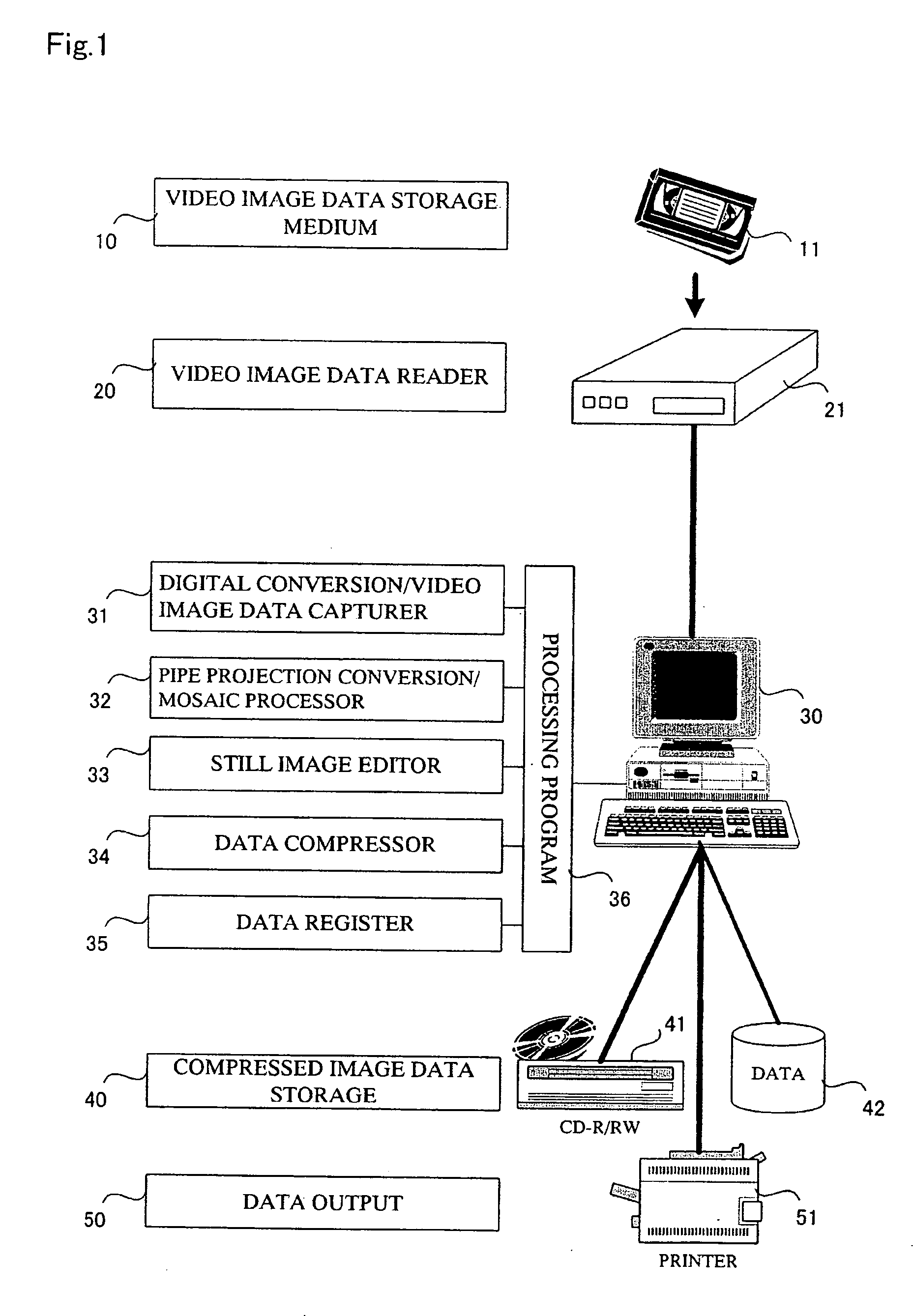
[0034]FIG. 1 is a diagram illustrating one example of the configuration of a system according to the present invention. A personal computer 30 is an essential component of the system, and includes a digital conversion / video image data capturer 31, a pipe projection conversion / mosaic processor 32, a still image editor 33, a data compressor 34, a data register 35 and a processing program 36.

[0035] A videocassette recorder 21 connected to the personal computer 30 is one example of a video image data reader 20, which reads video image data on an inner wall of a tubular object photographed by a video camera, not shown, and recorded in a video tape 11 exemplifying a video image data storage medium 10, and then, transmits it as a data signal to the personal computer 30.

[0036] A CD-R / RW drive 41 and a hard disk 42, both of which are connected to the persona...


PUM


Abstract

An image processing system automatically generates a seamless and continuous developed still image with little distortion by creating a developed diagram in the circumferential direction of a tube from one frame of a video image of an inner wall of a tubular object photographed by a video camera while moving in the axial direction of the tubular object and stitching the developed diagrams with each other in the longitudinal direction (i.e., on a central axis) of the tube by mosaic processing.

Description

BACKGROUND OF THE INVENTION [0001] 1. Field of the Invention [0002] The present invention relates to a system for automatically generating a seamless and continuous developed still image by generating a developed diagram in the circumferential direction of a tube based on one frame of a video image of an inner wall of a tubular object photographed while moving in the axial direction of the tubular object, and then, stitching the developed diagrams in the longitudinal direction (i.e., on a central axis) of the tube by mosaic processing in order to examine the inner wall of the tubular object. [0003] 2. Description of the Related Art [0004] The inner wall of a tunnel, which is one kind of tubular objects (for example, a building structure such as a tunnel, a water supplying pipe and tubular organs of human beings or animals such as esophagus, stomach, large intestine, small intestine, rectum, blood vessel, urethra, ureter, urinary bladder and trachea are regarded as the tubular object...

Claims


Application Information

Patent Timeline
IPC IPC(8): G01N21/954G06T3/40G06V10/24H04N5/225H04N5/228
CPCG01N21/954G06K9/32H04N2005/2255G06T3/4038G06K2009/2045G06V10/16G06V10/24H04N23/555
Inventor AKIZUKI, NAOMICHIYOSHIDA, NAOMISUHARNO, AGUS
Owner AKIZUKI NAOMICHI
Why Eureka
Try Eureka