
Air conditioning apparatus and ion generating device for use therein

Inactive Publication Date: 2005-08-04
SHARP KK
View PDF2 Cites 45 Cited by
  • Summary
  • Abstract
  • Description
  • Claims
  • Application Information

AI Technical Summary

Benefits of technology

[0009] According to one aspect of the present invention, an air conditioning apparatus is provided with an ion generating device that generates H+(H2O)m (where m is a natural number) as positive ions and O2−(H2O)n (where n is a natural number) as negative ions. This makes it possible to kill airborne bacteria by the action of H+(H2O)m as positive ions and O2−(H2O)n as negative ions, contributing to the conditioning of air.
[0010] According to another aspect of the present invention, an air conditioning apparatus generates H+(H2O)m (where in is a natural number) as positive ions and O2−(H2O)n (where n is a natural number) as negative ions and blows out these ions into the air so as to kill airborne bacteria through an oxidation reaction by hydrogen peroxide H2O2 or radical hydroxyl .OH generated as a radical through a chemical reaction between the negative and positive ions. This makes it possible to condition the air to be free from airborne bacteria and healthful.

Problems solved by technology

However, in regions with a poor outdoor environment, it is necessary to condition air artificially by some means to obtain comfortable air.
However, filters are subject to poorer performance after an extended period of use, and thus inevitably require some form of maintenance such as replacement.
In addition, it is difficult to ensure sufficiently high filtering performance to trap airborne bacteria effectively.
However, negative ions diminish as they bond to particular substances.
This may cause the discharge needle or another electrode to become frosted, leading to a short circuit.
Moreover, the flow of air is disturbed as it hits the discharge needle unit.
This may cause uneven blowing of air and a loss in the volume of air blown out, both undesirable effects in an air conditioner.
A high concentration of ozone is hazardous to the human body, such as by affecting the respiratory organs.

Method used


Image

  • Air conditioning apparatus and ion generating device for use therein
  • Air conditioning apparatus and ion generating device for use therein
  • Air conditioning apparatus and ion generating device for use therein

Examples


second embodiment

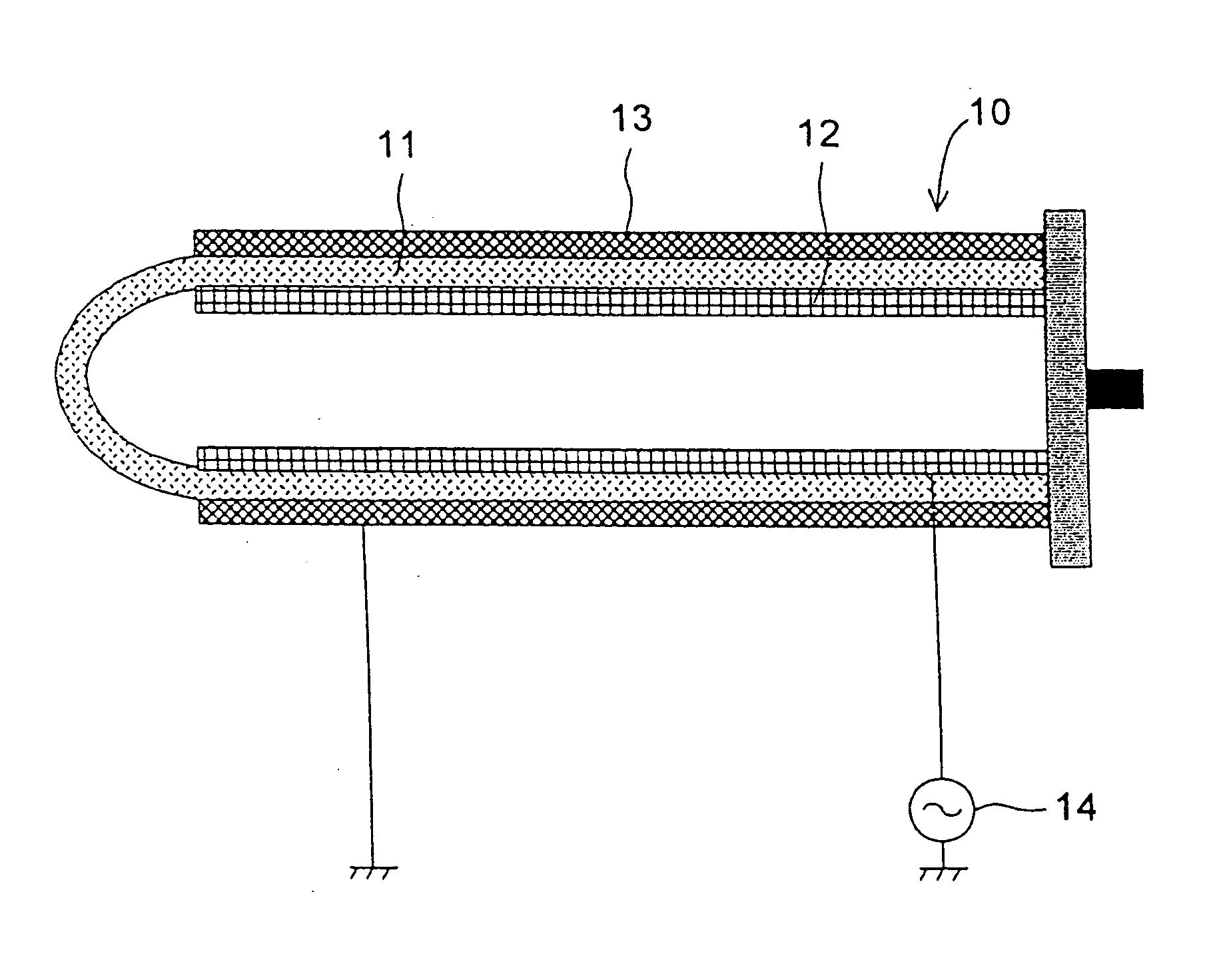
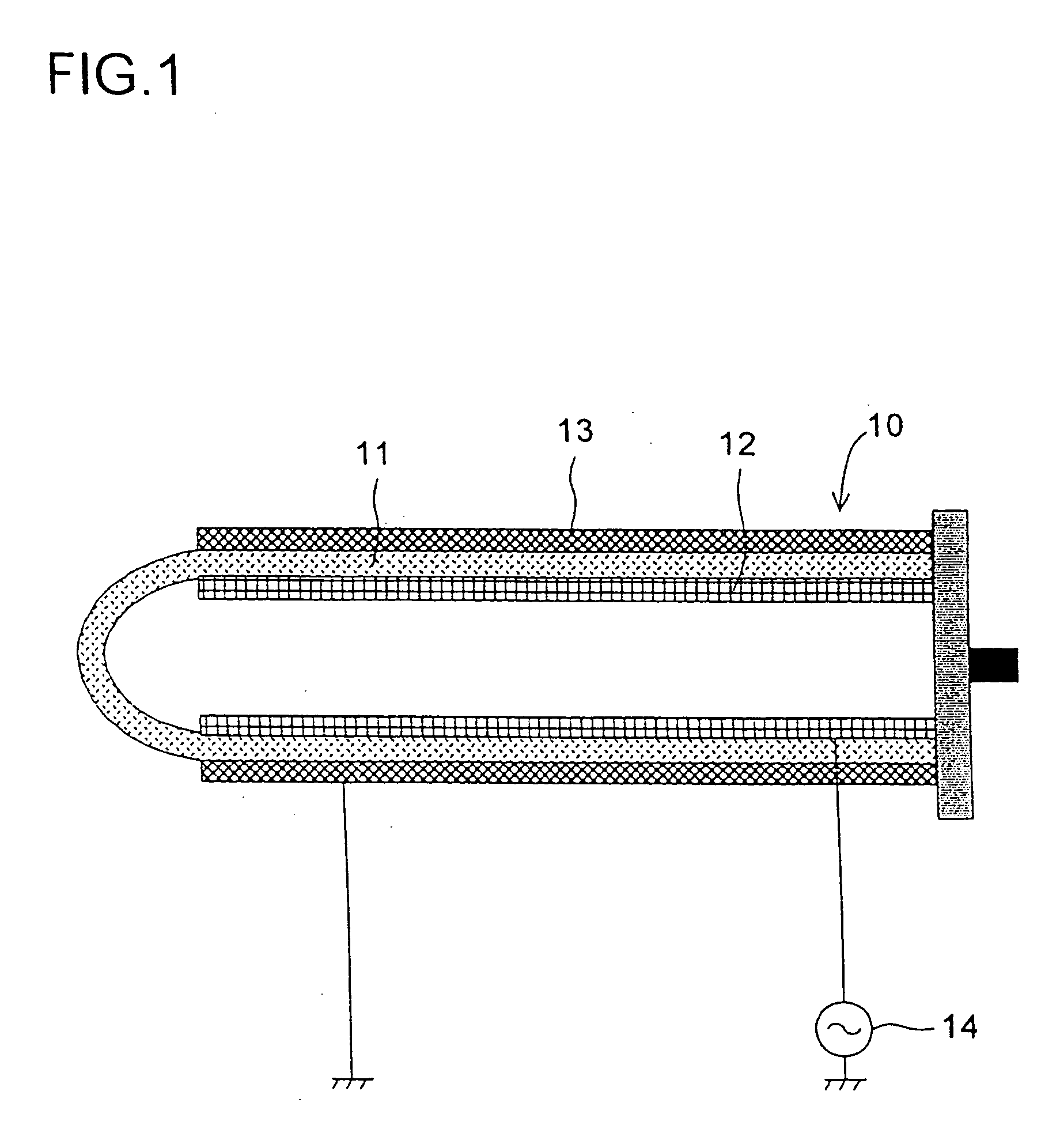
[0208] As in the second embodiment, when a high alternating-current voltage is applied between the inner and outer electrodes 62 and 63, plasma discharge occurs, generating positive ions consisting mainly of H+(H2O)n when the applied voltage is positive and negative ions consisting mainly of O2−(H2O)m when the applied voltage is negative.

[0209] As FIGS. 7 and 8 show, on the inner surface of the electrode housing portion 55a of the front cover 55, and also on the inner surface of the electrode cover 58, three ribs 68 (an element support portion) are formed integrally therewith at each end. The ribs 68 are composed of R portions 68a and elevated portions 68b that are made higher than the R portions 68a (see FIG. 5). Of the three ribs 68, the R portions 68a make contact with the peripheral surface of the cap 64 or 65, and therefore the rib at the center is made lower than the ribs on both sides.

[0210] The elevated portions 68b keep the ion generating element 54 in position in the late...

sixth embodiment

[0272]FIG. 25 shows a block diagram of the control system of the air conditioner of the To the input side of a controller 190 are connected a power switch 191 with which the operation of the air conditioner is turned on / off and a commercial power source 192 from which electric power is supplied to the controller 190. On the other hand, to the output side of the controller 190 are connected a compressor 142 that constitutes a key element for a refrigerating cycle of the air conditioner, an indoor fan 126, and, through the high frequency circuit 14, the inner electrode 12 of the ion generating device 10.

[0273] Thus, in the air conditioner of the sixth embodiment, in concert with the operation of the air conditioner, i.e. the operation of the compressor 142 and the indoor fan 126, the controller 190 can activate the high frequency circuit 14 to apply an alternating-current voltage to the inner electrode 12 of the ion generating device 10.

[0274] Thus, for example, when the air conditi...

tenth embodiment

[0288] the air conditioning apparatus of the invention will be described below with reference to FIGS. 29 to 31. FIG. 29 shows the indoor unit 101 f of this air conditioner with the front panel 103 closed, and FIG. 30 shows the indoor unit 101f with the front panel 103 opened. FIG. 31 is a block diagram of the control system of the air conditioner.

[0289] In the tenth embodiment, an ion outlet is provided separately from the air outlet 104 of the indoor unit 101f. In the figures, reference numeral 200 represents the ion outlet through which the ions generated by the ion generating device 10 is blown out, and behind this ion outlet 200 is arranged a blowing fan 201 (see FIG. 31) that blows out the ions generated by the ion generating device 10 that is provided separately from the air conditioning portion (composed of the compressor 142, the indoor fan 126, and other components).

[0290] The liquid crystal display device 106 displays the operation status of the ion generating device 10 ...


PUM


Abstract

An air conditioning apparatus incorporates an ion generating device that generates positive and negative ions by applying an alternating-current voltage between electrodes. The generated positive and negative ions coexist in the air and, when they attach to the surfaces of airborne bacteria, they react chemically with each other and generate radical hydroxyl and hydrogen peroxide, which extract hydrogen atoms from the cells of the bacteria and thereby kill them. This sterilizing effect is combined with the temperature-conditioning, dehumidifying, humidifying, air-purifying, and other functions of the air conditioning apparatus to bring about a comfortable and healthful indoor environment.

Description

TECHNICAL FIELD [0001] The present invention relates to an air conditioning apparatus, and particularly to an air conditioning apparatus incorporating an ion generating device. An air conditioning apparatus refers to any apparatus that alters the various factors determining the properties of air, such as the temperature and humidity thereof and the substances contained therein, so as to make it comfortable and healthful to the human body. Practical examples of air conditioning apparatus include air conditioners, dehumidifiers, humidifiers, air purifiers, refrigerators, fan heaters, microwave ovens, laundry driers, vacuum cleaners, and sterilizers. These air conditioning apparatus are aimed at conditioning the air inside a finite space, such as a room in a house or a building, a sickroom or operating room in a hospital, the inside of a car, aircraft, or vessel, or the inside of a warehouse or refrigerator. BACKGROUND ART [0002] It is needless to say that air plays an important role i...

Claims


Application Information

Patent Timeline
IPC IPC(8): A61L9/22F24F1/0063F24F1/0067F24F1/0076F24F1/0083F24F1/0087F24F3/14F24F3/16F24F13/28H01T23/00
CPCA61L9/22Y02B30/78F24F1/0011F24F1/0059F24F3/1423F24F3/166F24F13/28F24F2001/0048F24F2003/1446F24F2003/1664F24F2003/1671F24F2003/1682F24F2011/002F24F2011/0023F24F2011/0024F24F2011/0068F24F2203/1016F24F2203/1032F24F2203/1056F24F2203/1068F24F2203/1084H01T23/00F24F1/0007F24F2110/60F24F2110/64F24F2110/62F24F11/56F24F1/0057F24F8/26F24F8/20F24F8/192F24F8/30Y02A50/20Y02B30/70F24F1/0087F24F1/0067F24F1/0076F24F1/0063F24F1/0083
Inventor SEKOGUCHI, YOSHINORIMORIKAWA, MAMORU
Owner SHARP KK
Learn More