Power supply for use in an electronic energy meter

a technology of electronic energy meters and power supplies, applied in the direction of power conversion systems, dc-dc conversion, instruments, etc., can solve the problems of drawbacks of current available power supplies, reduce the on-time of transformers, prevent further current flow through primary windings, and accurately maintain constant output voltages

Inactive Publication Date: 2005-08-04
TRANSDATA
View PDF9 Cites 53 Cited by
  • Summary
  • Abstract
  • Description
  • Claims
  • Application Information

AI Technical Summary

Benefits of technology

[0006] The power supply includes a transformer that has a primary winding that receives the line voltage and a secondary winding, where stored energy from the primary winding is discharged to the secondary winding. The secondary winding of the transformer creates and provides the output voltage for the power supply. A switch is connected to the primary winding of the transformer for selectively permitting and preventing the flow of current through the primary winding. When current is flowing through the primary winding, the core of the transformer is magnetized and no energy is flowing to the secondary winding. When the current path through the primary winding is broken, current is prevented from flowing through the primary winding and the stored energy in the primary winding is transferred to the secondary winding of the transformer to create an output voltage. The value of the output voltage is dictated by controlling the amount of time current is allowed to flow through the primary winding. The on and off time of the switch connected to the primary winding thus controls the output voltage at the secondary winding.
[0007] A control circuit is coupled to the switch to provide a control signal to the switch to control the cyclic operation of the switch between the on and off positions. Preferably, the control circuit is a timer having on and off cycle times that are accurately controllable. Thus, the control signal from the control unit controls the cycle time of the switch, and thus the output voltage of the power supply.
[0008] In one embodiment of the invention, an over voltage circuit is positioned to receive the half-wave rectified line voltage. The over voltage circuit compares the rectified line voltage to an upper voltage limit. If the value of the rectified line voltage exceeds the upper voltage limit, the over voltage circuit disables the generation of the control signal from the control unit to the switch. When the control signal is disabled, the current path through the primary winding of the transformer remains open such that current can no longer flow through the transformer. When current is prevented from flowing through the transformer, energy is not induced on the secondary winding of the transformer. Since energy is not being reflected from the secondary winding, no additional reflected voltage is present at the primary winding, thereby reducing the total voltage as seen by the switch of the power supply circuit. In this manner, the over voltage circuit limits the voltage present at the switch to protect the switch of the power supply circuit.
[0011] The control circuit of the power supply circuit generates a control signal having a constant off time and a variable, controllable on-time. The on time of the control signal is inversely proportional to the value of the line voltage. In this manner, the control signal decreases the on time of the transformer for higher line voltages and increases on time when the line voltage is at a lower value. This feature allows the control circuit to more accurately maintain a constant output voltage for varying line voltages.

Problems solved by technology

Although switching power supplies and voltage dividers are known for use in an electronic electricity meter, drawbacks exist with the currently available power supplies.

Method used


Image

  • Power supply for use in an electronic energy meter
  • Power supply for use in an electronic energy meter
  • Power supply for use in an electronic energy meter

Examples


Embodiment Construction

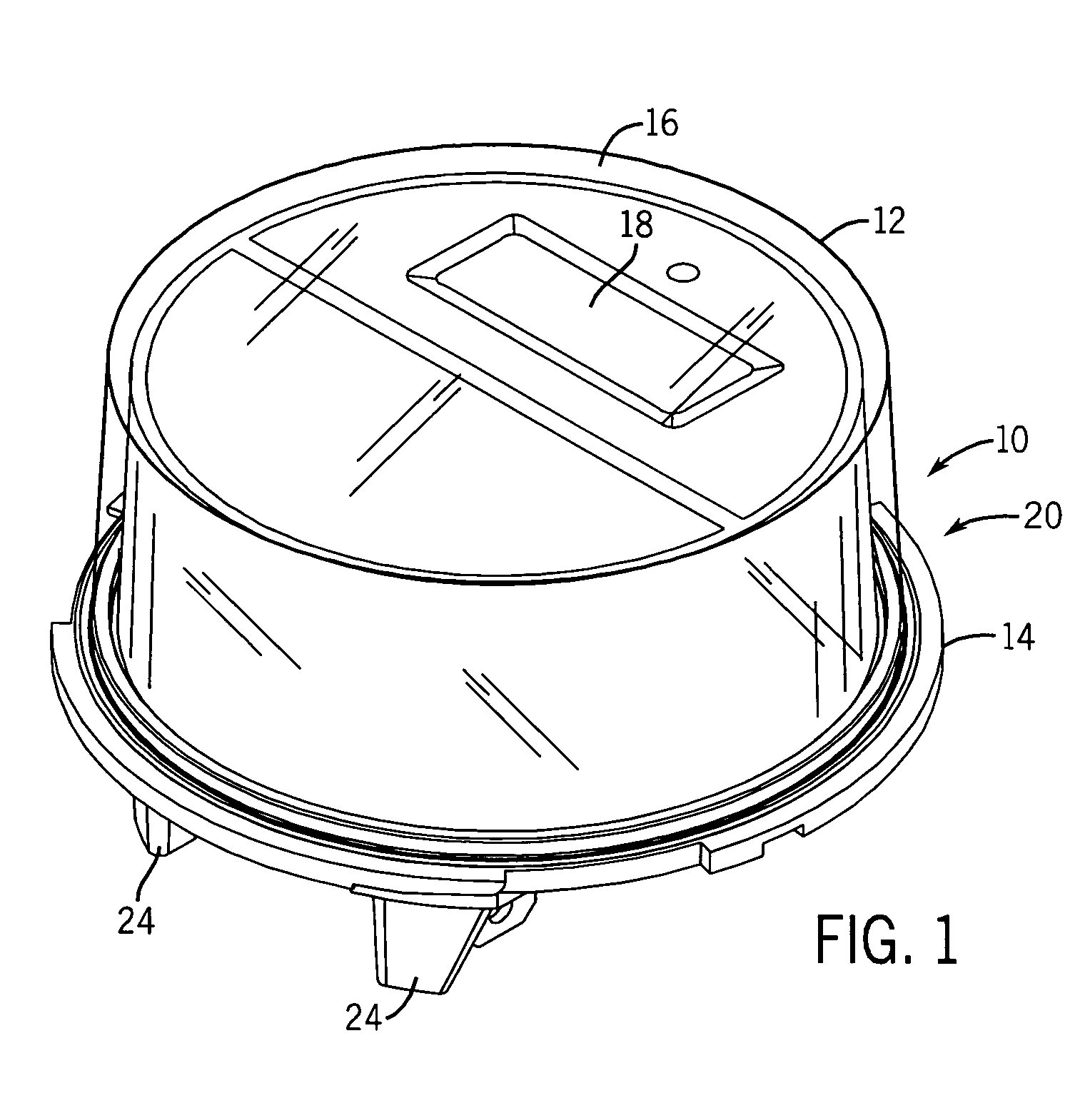
[0018]FIG. 1 illustrates a three-phase electronic electricity meter 10 constructed in accordance with the present invention. The electricity meter 10 includes an enclosed meter housing comprised of a cover member 12 mounted to a base member 14. The cover member 12 includes a generally clear face surface 16 that allows a digital display 18 to be read from the exterior of the electricity meter 10. The cover member 12 and base member 14 are joined to each other in a conventional manner such that the base member 14 and the cover member 16 define a sealed, enclosed meter housing. The meter housing prevents moisture and other environmental contaminants from reaching the internal circuitry contained within the three-phase electronic electricity meter 10.

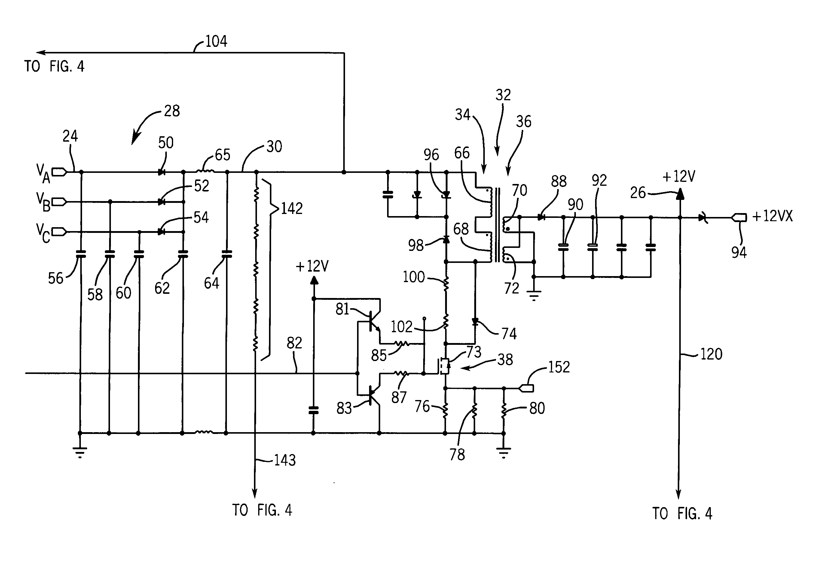
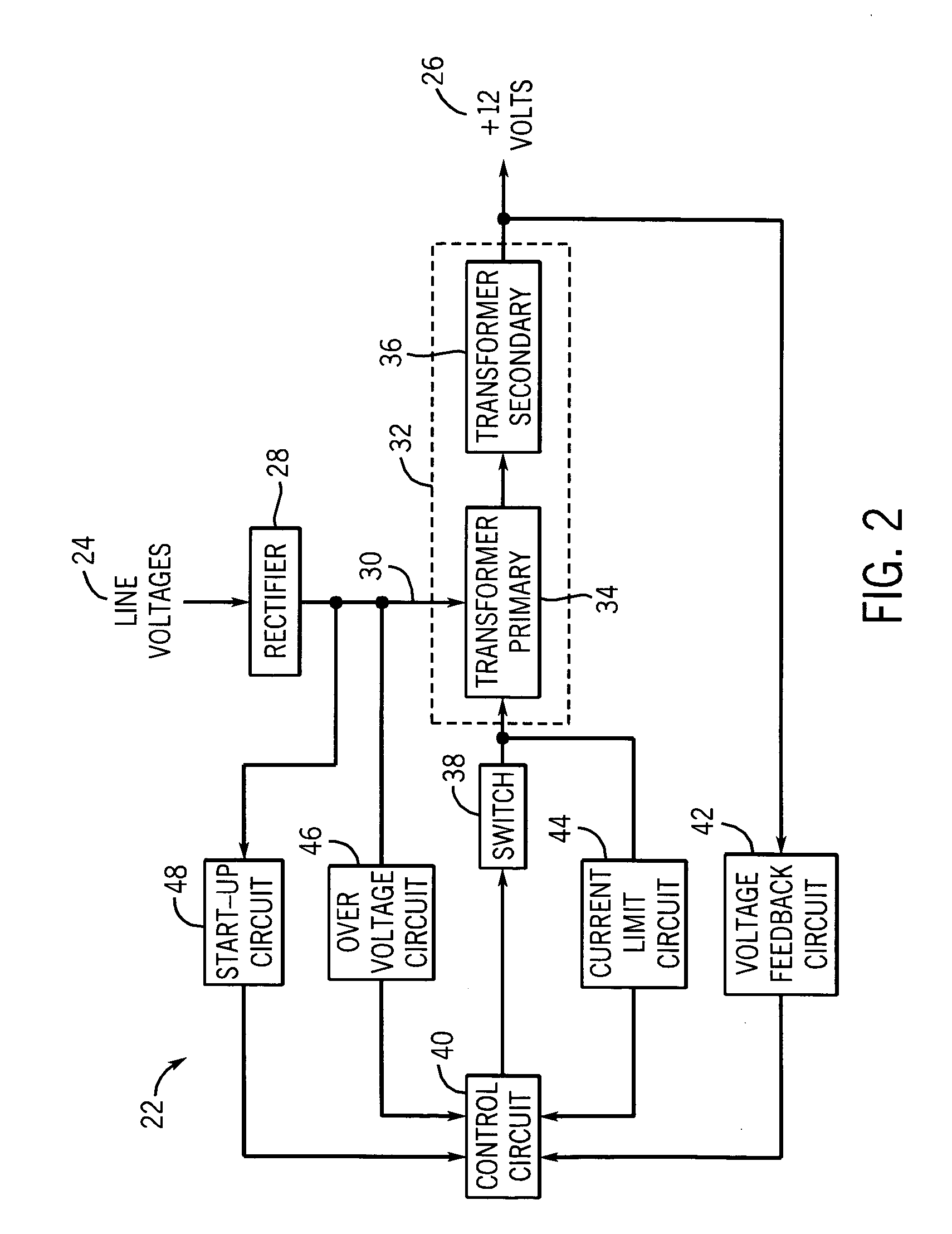
[0019] In the present invention, an operating and measurement circuit is contained within the meter housing that operates to measure the energy consumption and control the digital display 18. The specific details of the measurement circuit...


PUM


Abstract

A three-phase electronic electricity meter that includes a power supply circuit operable to create a constant voltage output when receiving a variable voltage input. The power supply circuit of the electricity meter receives a three-phase line voltage and converts the variable three phase line voltage to a constant DC output. The power supply circuit includes a current limiting circuit to suspend operation of the power converter when the current exceeds a selected value. The power supply circuit includes an over voltage protection that limits the maximum voltage applied to the switching component of the power supply circuit. Both the over voltage protection circuit and the current limiting circuit suspend operation of the power converter to prevent damage to the operating components of the power supply circuit.

Description

CROSS-REFERENCE TO RELATED APPLICATION [0001] The present application is based on and claims priority to British Patent Application Serial No. 0402319.8 filed on Feb. 3, 2004. BACKGROUND OF THE INVENTION [0002] The present invention generally relates to the field of electronic electricity meters. More specifically, the present invention relates to a power supply for providing power to operate the electronic monitoring circuitry contained within an electronic electricity meter. An electricity metering system monitors power lines to derive polyphase input representations of voltage and current. Because electrical uses by different consumers can vary significantly, a typical utility providers require different meters for monitoring various primary voltages. Currently, available meters exist that utilize both electromechanical and electronic circuitry to monitor the voltage and current consumption. [0003] It has been recognized that a solid state electronic electricity meter provides a ...

Claims


Application Information

Patent Timeline
Patent Type & Authority Applications(United States)
IPC IPC(8): H02M1/00H02M1/32H02M3/335
CPCH02M3/33507H02M1/32
Inventor KNILL, ALEX C.
Owner TRANSDATA
Why Eureka
Try Eureka