Radiographic imaging control apparatus and method

a control apparatus and radiographic imaging technology, applied in the direction of material analysis using wave/particle radiation, instruments, applications, etc., can solve the problems of affecting diagnosis, difficult to accurately estimate the primary radiation dose transmitted through the patient b, and difficult to perform an imaging process under appropriate x-ray dose control using aec, etc., to achieve the effect of easy imaging process

Active Publication Date: 2005-08-04
CANON KK
View PDF1 Cites 82 Cited by
  • Summary
  • Abstract
  • Description
  • Claims
  • Application Information

AI Technical Summary

Benefits of technology

[0014] The present invention has been made in consideration of the above situation, and has as its object to clearly specify the positions of respective detection regions of an automatic exposure control (AEC) device on a radiographic image, and to allow an easy imaging process under appropriate radiation dose control using AEC.
[0018] According to the present invention, since the positions of respective detection regions of an automatic exposure control (AEC) device on a radiographic image can be clearly specified, an imaging process can be easily made under appropriate radiation dose control using AEC.

Problems solved by technology

For this reason, it is difficult to accurately estimate primary radiation dose transmitted through the patient 109 before imaging.
Furthermore, when the AEC device 1004 is superimposed on a patient image, it becomes an artifact.
However, in the aforementioned X-ray imaging apparatus, when the AEC regions (A, B, and C) are not appropriately selected, or when positioning of the patient is incorrect, AEC does not function normally and results in an insufficient dose, and the image graininess drops, thus adversely influencing diagnosis.
Conventionally, since the operator cannot immediately recognize any selection errors of AEC regions or any deviations of AEC regions from the regions of interest, it is difficult to perform an imaging process under appropriate X-ray dose control using AEC.
Especially, in case of a side imaging process of a body, individual differences are large, and it is difficult to determine the position of interest of a spine from outside due to a different body thickness.
Hence, even when the imaging process is repeated, appropriate X-ray dose control cannot be done based on correct AEC.

Method used


Image

  • Radiographic imaging control apparatus and method
  • Radiographic imaging control apparatus and method
  • Radiographic imaging control apparatus and method

Examples


first embodiment

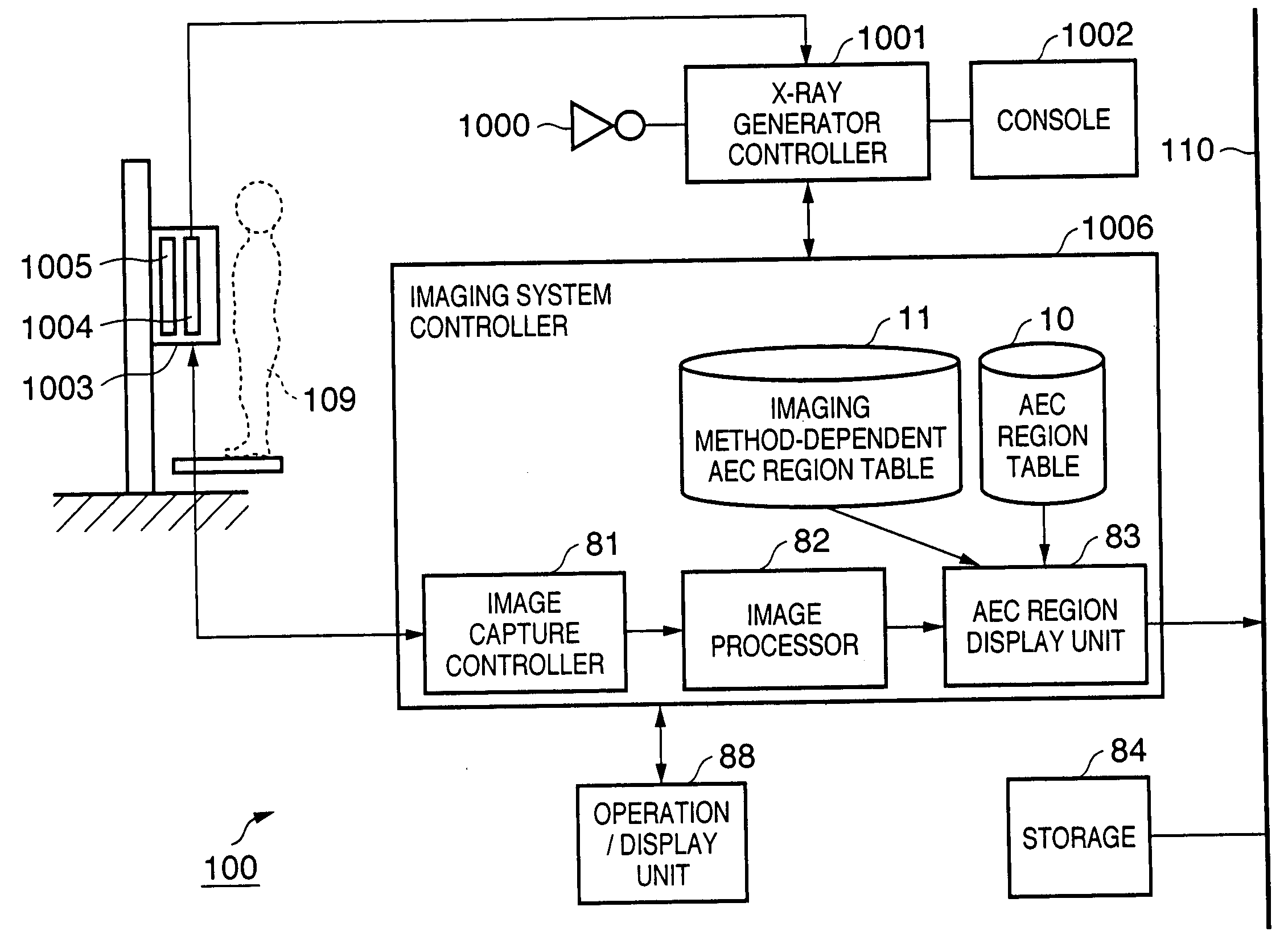
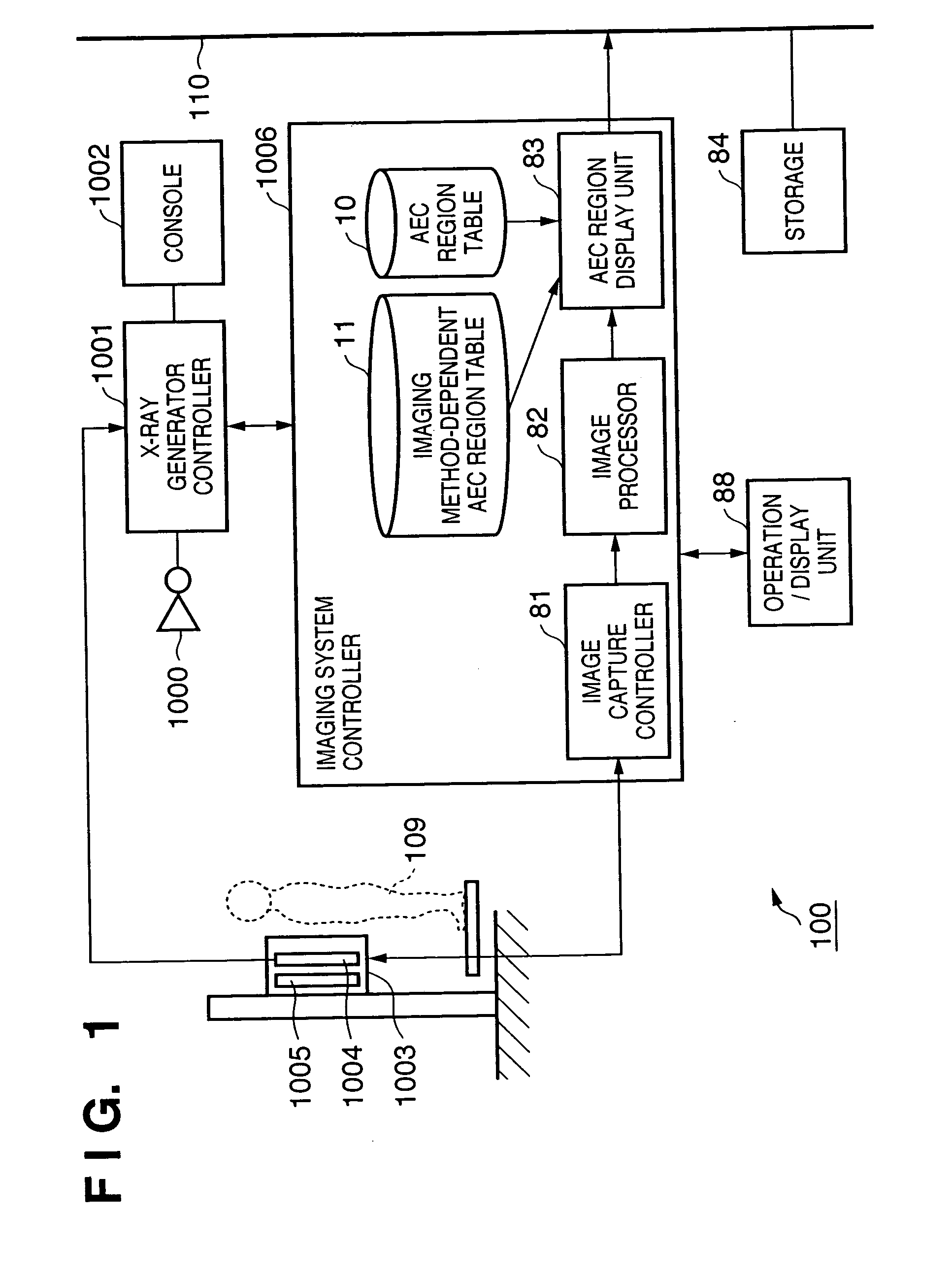
[0038]FIG. 1 is a block diagram showing the arrangement of an X-ray imaging system 100 according to the first embodiment. The X-ray imaging system 100 comprises an X-ray tube 1000, X-ray generator controller 1001, X-ray generator console 1002, imaging unit 1003, and the like, which have been explained using FIG. 15. An imaging system controller 1006 processes a digital image signal obtained from the imaging unit 1003, and makes various kinds of control for an X-ray generator.

[0039] The X-ray generator controller 1001 controls application of a high voltage to the X-ray tube 1000 in accordance with the imaging conditions such as a tube current, tube voltage, irradiation time, and the like, which are sent from the X-ray generator console 1002 and imaging system controller 1006, and an AEC signal from an AEC device 1004.

[0040] The imaging unit 1003 includes an X-ray detector 1005 which detects X-rays emitted by the X-ray tube 1000 and obtains a digital image, the AEC device 1004 which...

second embodiment

[0077] The second embodiment will explain a case wherein patient information and AEC region information are transferred from the HIS, RIS, and X-ray generator (X-ray generator controller 1002).

[0078]FIGS. 10A and 10B partially show imaging request information transferred from the HIS, RIS, and generator. FIG. 10A shows patient information and imaging portion information transferred from the HIS or RIS before X-ray exposure. FIG. 10B shows execution information sent from the generator after X-ray exposure. Note that the execution information in FIG. 10B may be received via the HIS or RIS in place of being directly received from the generator.

[0079] A case will be explained first with reference to the flowchart of FIG. 11 wherein patient information and imaging method information (including a portion to be radiographed, imaging direction, and the like) are received from the HIS or RIS, and AEC regions (or region) are settled using these pieces of information before X-ray exposure (b...

third embodiment

[0086] In the first and second embodiments described above, the operator presses the AEC display button 252 after imaging to superimpose valid AEC regions on a radiographic image. In the third embodiment, the validity of AEC regions is checked on the basis of image data, and if it is determined that AEC region settings obviously have a problem, AEC regions are automatically superimposed on a radiographic image. For example, when the average pixel value of each valid AEC region is apparently different from that in the AEC region in a normal imaging state, that AEC region is more likely to be incorrect. Hence, valid AEC regions are preferably displayed for the operator without waiting for depression of the AEC display button 252 by the operator.

[0087]FIG. 13 is a flowchart for explaining the process of the imaging system controller 1006 according to the third embodiment. Steps S1 to S6 are the same as those in the first embodiment. Of course, the processes up to step S6 may be replac...


PUM

PropertyMeasurementUnit
lengthaaaaaaaaaa
radiographic imagingaaaaaaaaaa
densityaaaaaaaaaa

Abstract

An X-ray imaging control apparatus acquires radiographic data obtained from an X-ray imaging apparatus which controls an X-ray dose upon X-ray imaging by detecting the X-ray dose in one or a plurality of detection regions, and displays a radiographic image on the basis of the acquired radiographic data. At this time, detection region information indicating the position and range of each detection region used in the X-ray imaging apparatus upon generating the radiographic data is acquired. Based on this detection region information, an image indicating each detection region is superimposed on the displayed radiographic image.

Description

FIELD OF THE INVENTION [0001] The present invention relates to a radiographic imaging apparatus which obtains a radiographic image by automatically controlling the dose of radiation on a patient. BACKGROUND OF THE INVENTION [0002] As an X-ray imaging apparatus that aims at medical diagnosis, an X-ray photography system using an X-ray detector that includes an intensifying screen and film. In recent years, a digital X-ray imaging system that generates an image by digitally detecting X-rays has prevailed in place of such X-ray photography system. Typical one of digital X-ray imaging apparatuses acquires an X-ray image using a flat panel sensor as a detection device. In this apparatus, a solid-state imaging element which has sensitivity to X-rays and converts and outputs an electrical signal corresponding to the detected X-ray intensity, or a unit which combines a phosphor that absorbs X-ray energy and emits fluorescence accordingly, and a photoelectric conversion element that has sens...

Claims


Application Information

Patent Timeline
Patent Type & Authority Applications(United States)
IPC IPC(8): H05G1/44A61B6/00G01N23/04H05G1/42
CPCA61B6/00A61B6/547A61B6/542A61B6/465
Inventor TAKASAWA, TORU
Owner CANON KK
Why Eureka
Try Eureka