Molecular separator

a separator and molecular technology, applied in the direction of separation process, membrane, piston pump, etc., can solve the problems of excessive discharge of detergents and other chemicals, undesirable presence of suspended and/or dissolved solids in water, wastewater and other fluids, etc., and achieve the effect of increasing filtration efficiency

Active Publication Date: 2005-08-04
TERVITA +1
View PDF23 Cites 16 Cited by
  • Summary
  • Abstract
  • Description
  • Claims
  • Application Information

AI Technical Summary

Benefits of technology

[0011] The present invention also discloses a novel poppet valve design which insures leak proof function and can be controlled electronically via standard control inputs or pneumatically by the application of positive or negative pressure. The present invention also discloses a novel separator design which utilizes kinetics and cavitation physics to increase filtration efficiency, allowing the separation of chemical sub-fractions from fluid streams below the 1 micron dimension.

Problems solved by technology

The safe and effective removal of contaminants from fluids is a consistent problem faced by many industries.
The presence of suspended and / or dissolved solids in water, wastewater and other fluids is undesirable for several reasons.
If established discharge-contamination levels are exceeded, cities and other governmental authorities may impose surcharges and penalties on the entity responsible for the excessive discharge.
Detergents and other chemicals used in the wash operations and drilling operations present further difficulties only increasing the effluent fluid discharge concerns.
However, where the cost of water is not a factor and the public sewage system can accept certain contaminants, a complete recycling system may not be cost justified.

Method used


Image

  • Molecular separator
  • Molecular separator
  • Molecular separator

Examples


Embodiment Construction

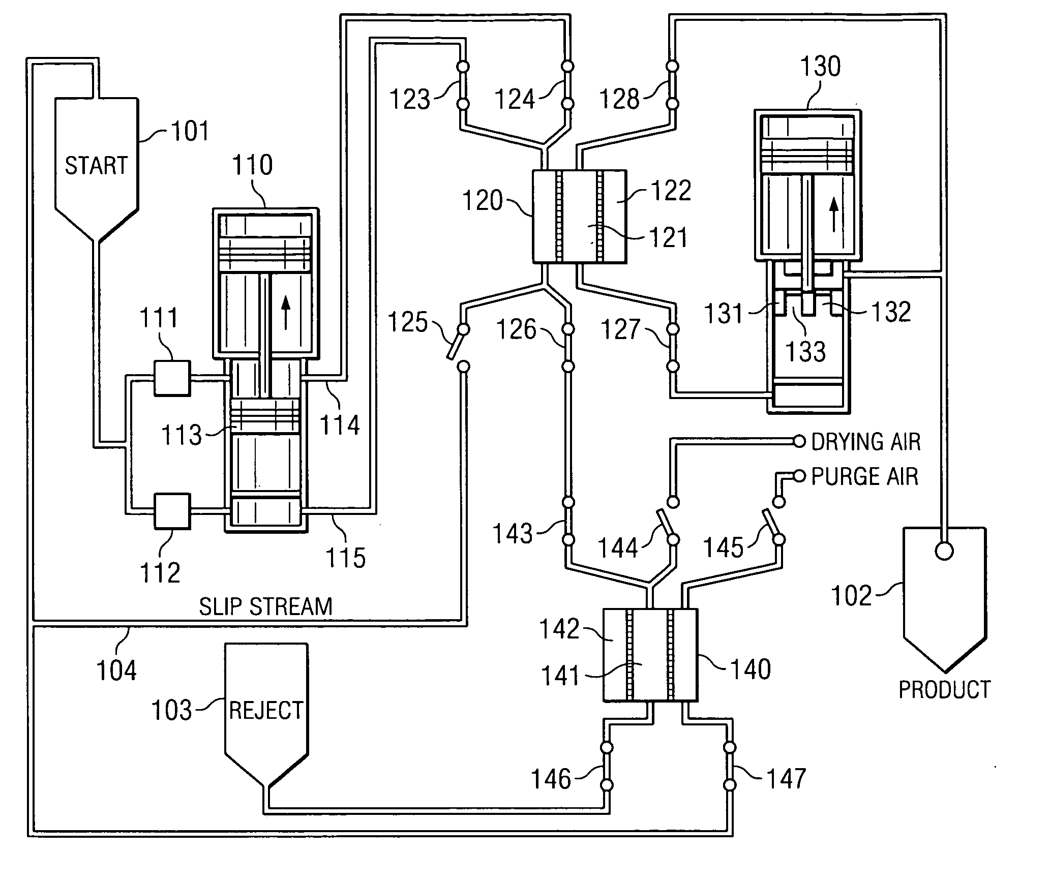
[0039] Referring now to FIG. 1, a schematic diagram illustrating the interaction of the functional components of the molecular separator is depicted in accordance with the present invention. An untreated fluid containing suspended particles and dissolved matter is placed in a in starting or contaminated fluid storage tank 101. This untreated fluid may include contaminated water, industrial solvents, or any similar fluid or solid from which sub-fractions are to be separated. The present invention can separate liquid from liquid, gases from liquids, and gases from solids. For example, the untreated fluid might be water contaminated with oil, iron, lead or other toxins or waste products. Another example of the fluid to be treated is brine made of zinc bromide (often used to flush drilling holes) from which dissolved solutes are removed such as iron.

[0040] The filtration process begins by drawing the untreated fluid from the starting tank 101 by means of a first pneumatic pump 110. The...


PUM

PropertyMeasurementUnit
particle sizesaaaaaaaaaa
time periodaaaaaaaaaa
pressureaaaaaaaaaa

Abstract

The present invention discloses a method and apparatus for separating particles and dissolved matter from a fluid stream. Specifically, the present invention includes a first pressure source which transports untreated fluid into a separator annulus with a filter element disposed therein. The untreated fluid is placed under appropriate pressure sufficient to produce turbulent flow, increased particle kinetics and / or cavitation physics allowing the desired fluid to penetrate and pass into and through the filter media. The filtered fluid is then transported to a collection tank. The contaminant particulate matter retained on the exterior of the filter media may be removed by the instantenous reverse pressurization of the separator annulus by a second pressure source thereby removing the contaminant particles away from contact with the filter media, and which may then be transported to a waste collection tank or a concentrator for further treatment.

Description

PRIORITY CLAIM [0001] This application claims the benefit of U.S. Provisional Application No. 60 / 540,492, filed Jan. 30, 2004, the disclosure of which is incorporated herein by reference.BACKGROUND OF THE INVENTION [0002] 1. Technical Field [0003] The present invention relates to methods and apparatus for the physical separation of solids from fluids, and fluids from gases. More specifically, the invention relates to methods and apparatus for separating solids and dissolved constituents from fluids using an arrangement of separators and concentrators, which are pneumatically pressurized and depressurized at desired intervals via electronically controlled poppet valves, which results in the separation of particulates and dissolved constituents from the untreated fluid media. [0004] 2. Description of Related Art [0005] The safe and effective removal of contaminants from fluids is a consistent problem faced by many industries. The impurities accumulated by water and other fluids during...

Claims


Application Information

Patent Timeline
Patent Type & Authority Applications(United States)
IPC IPC(8): B01D17/02B01D61/00B01D61/14B01D61/18B01D61/20B01D63/06B01D65/00B01D65/02B01D65/08B64D11/00C02F1/44C02F11/12C12M1/34F04B9/113
CPCB01D17/0202B01D2313/125B01D61/14B01D61/142B01D61/18B01D61/20B01D63/06B01D65/00B01D65/02B01D2321/04C02F1/441F04B9/113B01D61/00B01D2313/105B01D61/22B01D2313/24C02F1/44C02F11/12C02F2201/006B01D17/085B01D61/146
Inventor JOHNSON, RAYMOND FORDJOHNSON, MARKLEY DEANGRAGE, RODNEY
Owner TERVITA
Why Eureka
Try Eureka