
Back up pad of grinding wheel

a back up pad and grinding wheel technology, applied in the field of grinding wheels, can solve the problems of insufficient flexibility of the back up pad b>20/b> for grinding wheels, increase production costs, etc., and achieve the effect of reducing the production cost of the back up pad and being thin and ligh

Inactive Publication Date: 2005-08-04
SUN ABRASIVES CORP
View PDF4 Cites 19 Cited by
  • Summary
  • Abstract
  • Description
  • Claims
  • Application Information

AI Technical Summary

Benefits of technology

[0006] It is, therefore, an object of the present invention to provide a back up pad of a grinding wheel which is flexible to allow the grinding wheel to grind curved portions and which is relatively thin and light, thereby decreasing the production cost thereof.

Problems solved by technology

Such a conventional back up pad 20 comprised of the glass fiber layer 22 is relatively thick and heavy, thereby increasing the production cost thereof.
Further, the back up pad 20 is not sufficiently flexible to allow the grinding wheel to grind curved portions of a workpiece.

Method used


Image

  • Back up pad of grinding wheel
  • Back up pad of grinding wheel
  • Back up pad of grinding wheel

Examples


Embodiment Construction

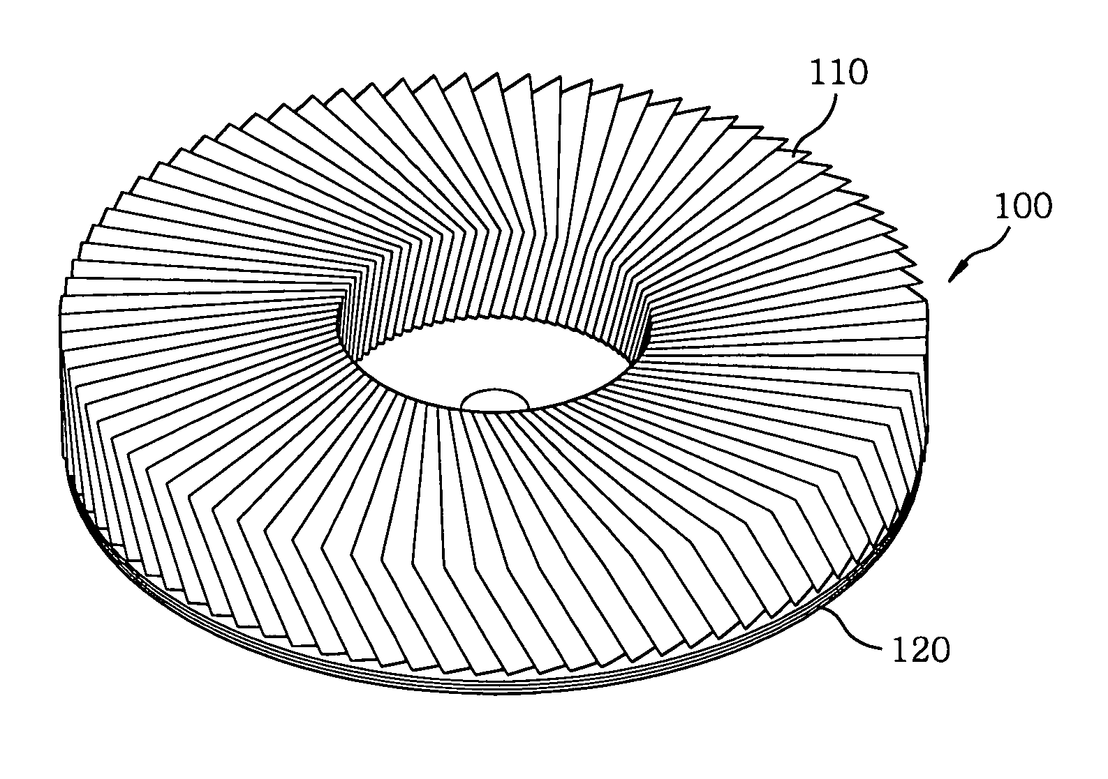
[0018] Referring to FIG. 4, there is illustrated a grinding wheel of a flap type in accordance with a preferred embodiment of the present invention. As shown in FIG. 4, a flap type grinding wheel 100 includes a back up pad 120, and a plurality of coated abrasives flaps 110 circumferentially arranged on the back up pad 120 and attached thereto by using, e.g., an epoxy adhesive.

[0019] Referring now to FIGS. 5, 6A and 6B, the back up pad 120 is constructed by thermally compressing a plurality of, e.g., two, glass fiber layers 122 with phenol novolac resin impregnated therein and a plurality of, e.g., two, carbon fiber layers 124. The back up pad 120 includes a central hub 111 for receiving a rotating shaft of a grinder (not shown). A non-woven sheet (not shown) may be attached to the bottom surface of the lowermost carbon fiber layer 124. Further, the coated abrasives flaps 110 are circumferentially arranged on the uppermost glass fiber layer 122 of the back up pad 120 and attached th...


PUM

PropertyMeasurementUnit
tensile strengthaaaaaaaaaa
flexibleaaaaaaaaaa
shapeaaaaaaaaaa

Abstract

A back up pad of a grinding wheel includes two glass fiber layers and two carbon fiber layer attached to the glass fiber layer. The glass fiber layers and the carbon fiber layer are thermally compressed. The carbon fiber layer has a fabric construction of about 40-80 s / yarn×20-35 s / yarn (warp×fill).

Description

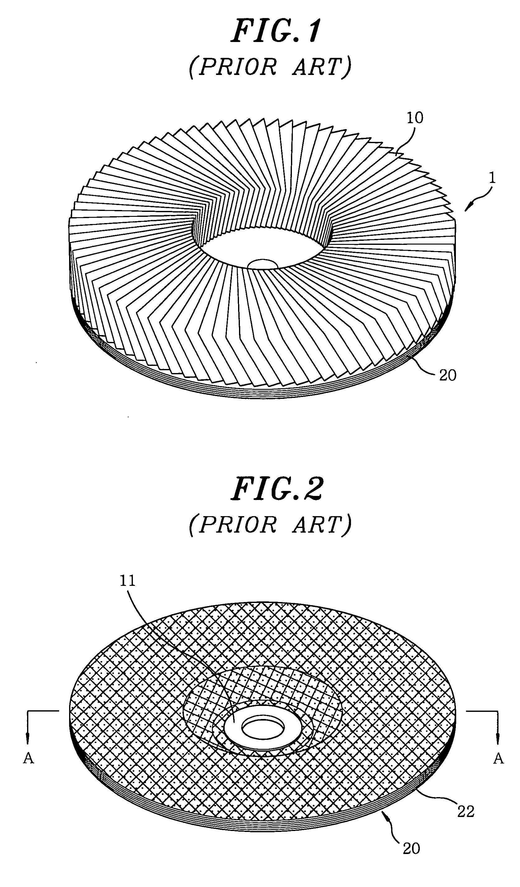
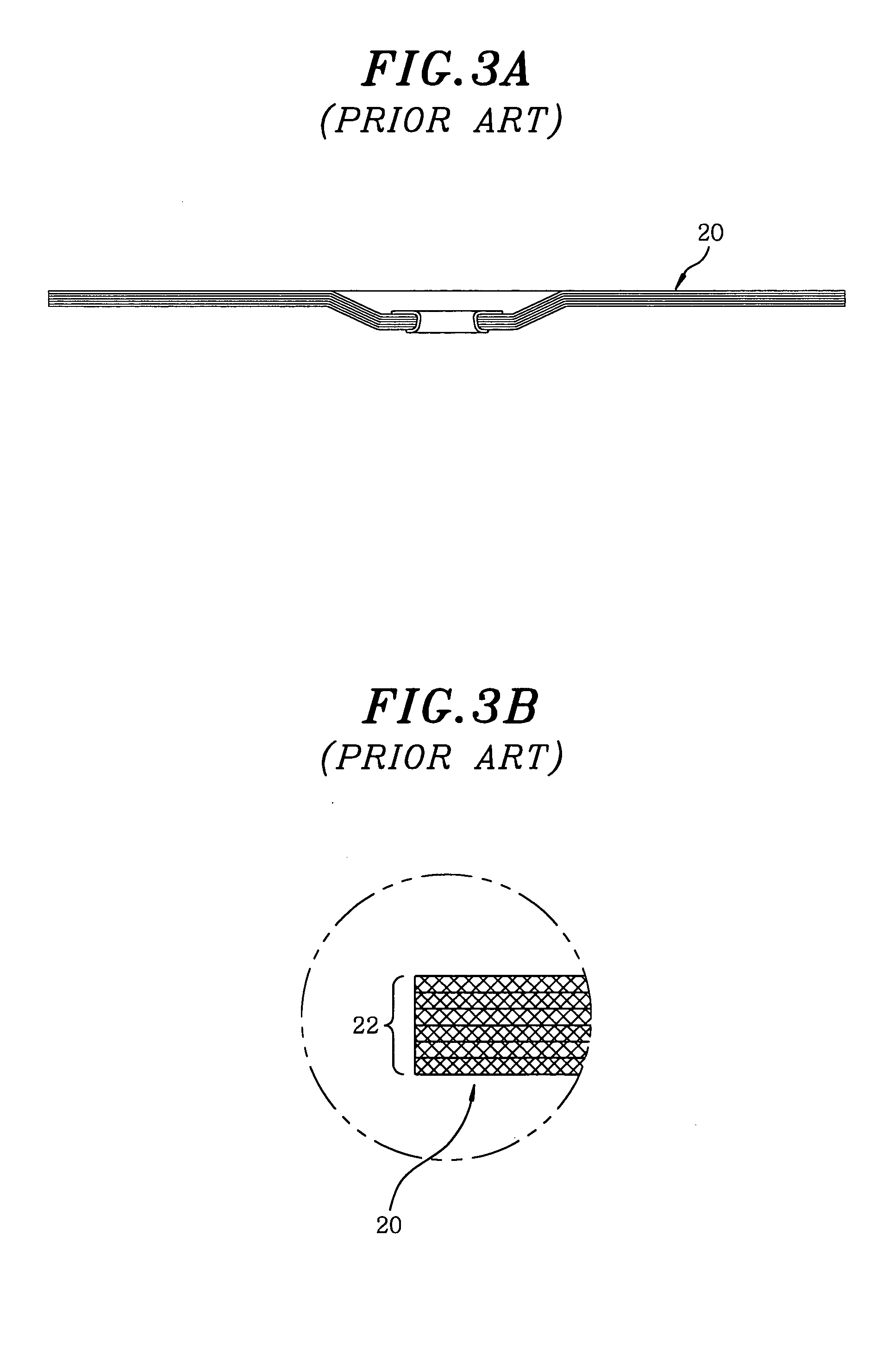
FIELD OF THE INVENTION [0001] The present invention relates to a grinding wheel; and, more particularly, to a back up pad of the grinding wheel which is flexible to allow the grinding wheel to grind curved portions and which is relatively thin and light, thereby decreasing the production cost thereof. BACKGROUND OF THE INVENTION [0002] Generally, a grinding wheel is mounted on a driving machine providing a rotational power thereto, and is used to grind a surface of a workpiece. [0003]FIG. 1 shows a perspective view of a conventional grinding wheel 1 of a so-called lamella or flap type, wherein a plurality of coated abrasives flaps 10 are circumferentially arranged and adhesively attached on a back up pad 20. [0004] Referring to FIGS. 2, 3A and 3B, the back up pad 20 is constructed by thermally compressing a plurality of, e.g., six, glass fiber layers with phenol novolac resin impregnated therein, and includes a central hub 11 for receiving a rotating shaft of a grinder (not shown). ...

Claims


Application Information

Patent Timeline
Patent Type & Authority Applications(United States)
IPC IPC(8): B24D13/16B24D13/20
CPCB24D13/20B24D13/16B24D13/00
Inventor SHIN, TONG SHIK
Owner SUN ABRASIVES CORP
Learn More