
Read-write processing apparatus and method for RFID tag

a processing apparatus and a technology of rfid tags, applied in the field of read-write processing apparatus and method of rfid tags, can solve the problems of difficult prediction, no sufficient noise prevention measures, and communication errors, and achieve high reliability, prevent communication errors, and carry out communication processes.

Active Publication Date: 2005-08-04
ORMON CORP
View PDF20 Cites 62 Cited by
  • Summary
  • Abstract
  • Description
  • Claims
  • Application Information

AI Technical Summary

Benefits of technology

[0011] It is therefore an object of this invention to make it possible for the user, when a communication error has occurred in a communication process with an RFID tag, to easily ascertain whether this error was due to noise or not.
[0012] It is another object of the invention to prevent the occurrence of a communication error with a high level of reliability by stopping the communication or preventing the start of a communication under a condition of a high noise level.

Problems solved by technology

With an RFID system as described above, there is a high probability that various kinds of noise will come to be mixed in the communication region for the tag and the antenna part so as to cause communication errors since the system is often introduced in an environment where machines and apparatus of various types are installed.
When such an RFID system is put in an actual use in a real situation, however, there is a possibility of a communication error due, for example, to a sudden occurrence of noise, say, because of the operations of surrounding machines.
It is difficult to predict, however, when and how such sudden noise may occur and the real situation is that no sufficient measure is being taken against noise.
This invention has problems, however, in that the process becomes complicated because special communications must be carried out between the read-write processing apparatus and the RFID tag for checking the status of noise and that the read-write processing apparatus is required to carry out two correlation calculation processes.
Under a circumstance where the variations of noise are large, furthermore, although a communication process may be started after it is ascertained that the two correlation values C1 and C2 both satisfy the aforementioned conditions, there may arise a sudden change in the noise and a communication error may result.
Moreover, communication errors are not limited to be caused by noise but may be caused also for reasons other than noise such as a fault in the RFID tag.
In the situation of a communication error, prior art systems inclusive of those according to aforementioned Japanese Patents Koho 2,610,897 and 9-190518 are not adapted to check whether or not it was caused by noise.

Method used

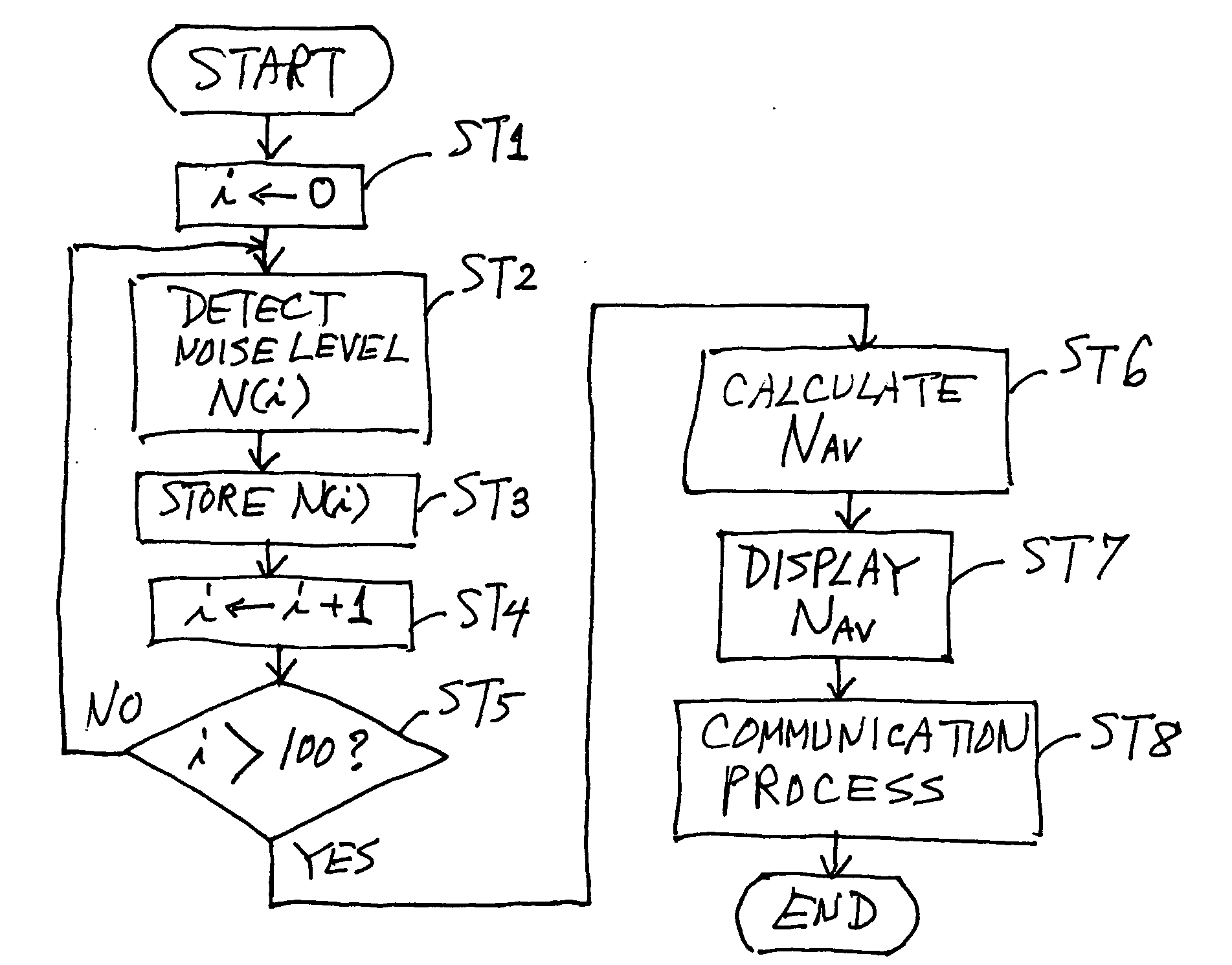

Image

  • Read-write processing apparatus and method for RFID tag
  • Read-write processing apparatus and method for RFID tag
  • Read-write processing apparatus and method for RFID tag

Examples


Embodiment Construction

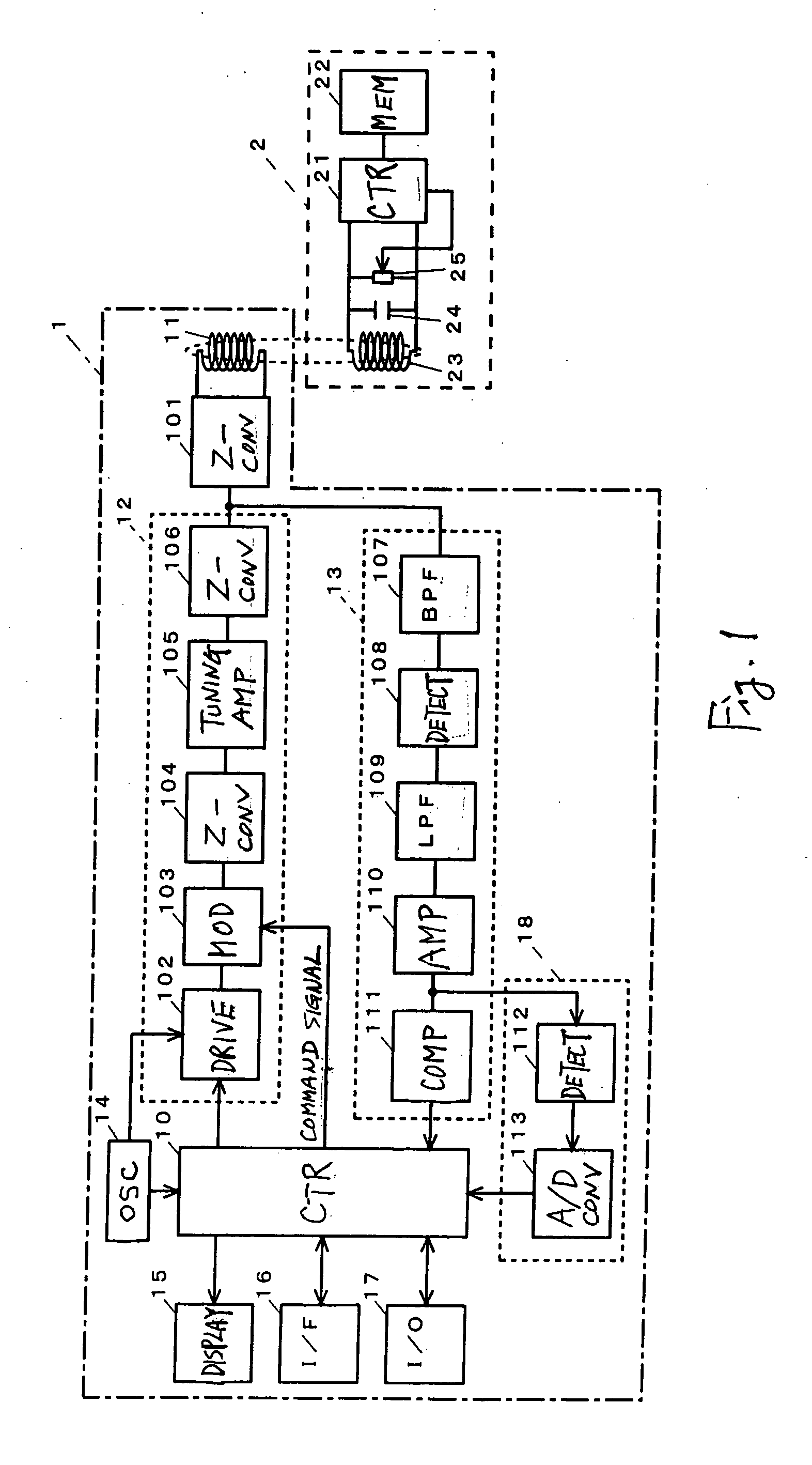
[0047]FIG. 1 is a block diagram showing the structure of a reader-writer 1 embodying this invention and an RFID tag (hereinafter referred to simply as a tag) 2 as its object of communication. The tag 2 in this example does not contain a power source, being of the type that operates by an induced electromotive force generated by transmitted waves from the reader-writer 1, and is provided with a control part 21 and a semiconductor memory 22. The tag 2 also comprises an antenna coil 23, a capacitor 24 and a load switch 25 (a resistor with a contact point, according to this example) for communication. The control part 21 of this tag 2 includes not only a computer but also peripheral circuits such as a demodulation circuit for demodulating transmitted signals from the reader-writer 1.

[0048] The reader-writer 1 is formed with a control part 10, an antenna coil 11, a transmitter circuit 12, a receiver circuit 13, an oscillator circuit 14 and a Z conversion circuit 101 for a matching proce...


PUM


Abstract

A read-write processing apparatus communicates with an RFID tag provided with a semiconductor memory to exchange commands and responses through antenna coils. A condition under which only a carrier wave is transmitted is set prior to a communication with the RFID tag and a level from a reception signal obtained under this condition is extracted as noise level. The extracted noise level is displayed or outputted to an output host apparatus.

Description

[0001] Priority is claimed on Japanese Patent Applications 2004-018255 filed Jan. 27, 2004 and 2005-004702 filed Jan. 12, 2005. BACKGROUND OF THE INVENTION [0002] This invention relates to a read-write processing apparatus for carrying out non-contact communications with an RFID tag containing a semiconductor memory to read out or write data from or into this memory and a read-write method that is carried out by such an apparatus. [0003] Systems having a memory medium storing various data attached to each article to be transported and being adapted to read and write data from and into this memory medium by wireless communications are coming to be introduced into control sites of cargoes and assembly lines of factories. Such a system is referred to as an RFID (radio frequency identification) system and the aforementioned memory medium to be attached to each article to be transported contains an IC chip containing a semiconductor memory and a communication antenna coil and is commonly...

Claims


Application Information

Patent Timeline
Patent Type & Authority Applications(United States)
IPC IPC(8): G06K7/00G06K17/00H01Q1/36H01Q7/00H01Q11/08H04B1/59H04B5/00H04B5/02H04L69/40
CPCG06K7/0008H01Q1/362H01Q7/00H04B5/0081H04B5/00H04B5/0056H04B5/0062H01Q11/08H04B5/77H04B5/26
Inventor ARIYOSHI, TOMONORIOZAKI, KOYOSAKACHO, KOJI
Owner ORMON CORP
Learn More