
Lifecycle support software tool

a software tool and lifecycle technology, applied in the field of software, can solve the problems of multiple component failure of products, inability to meet the mission of automobiles, and inability to meet the needs of consumers, etc., and achieve the effect of reducing support costs, facilitating decision-makers to be flexible, and saving costs

Inactive Publication Date: 2005-08-04
THE BOEING CO
View PDF4 Cites 10 Cited by
  • Summary
  • Abstract
  • Description
  • Claims
  • Application Information

AI Technical Summary

Benefits of technology

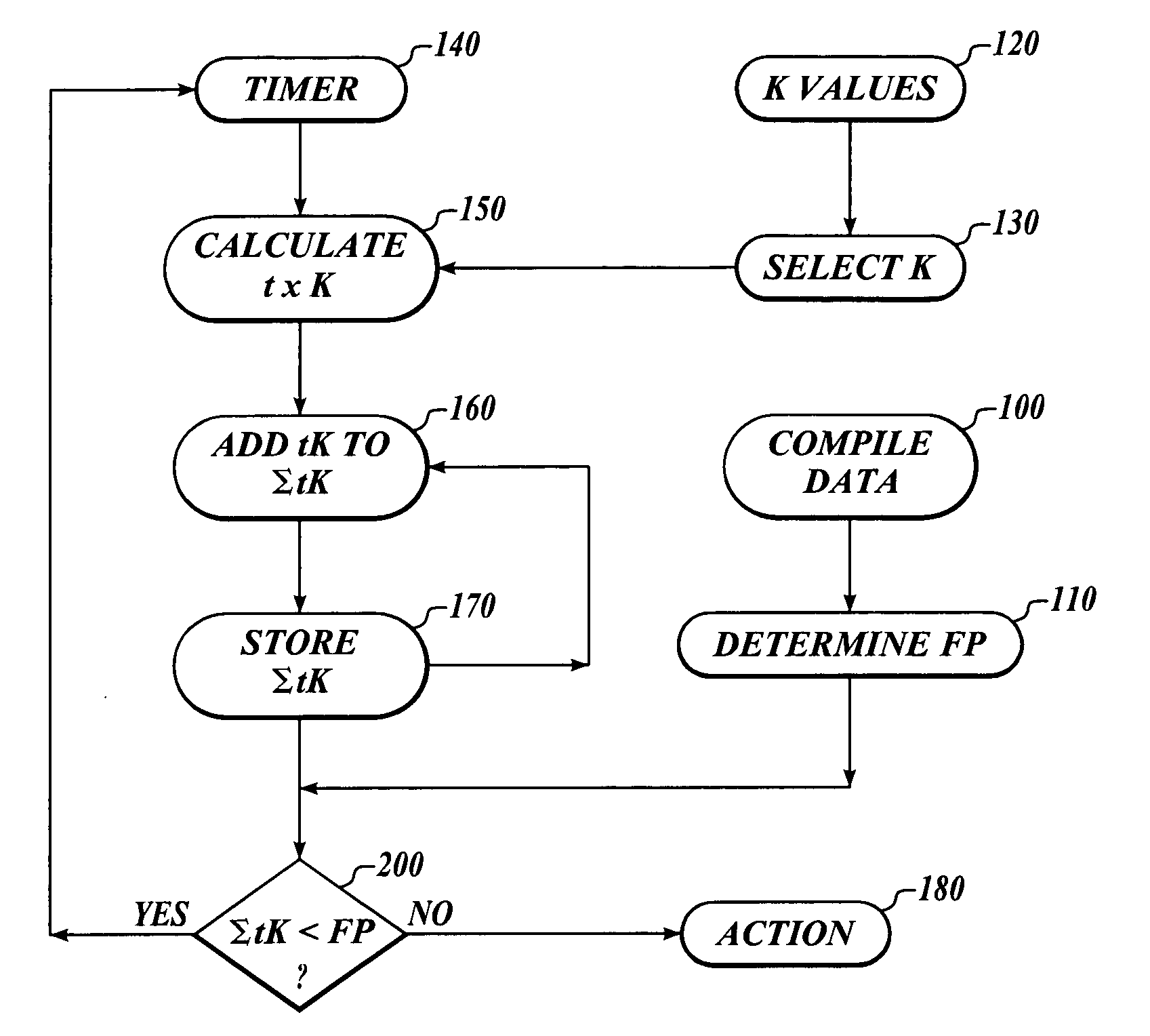
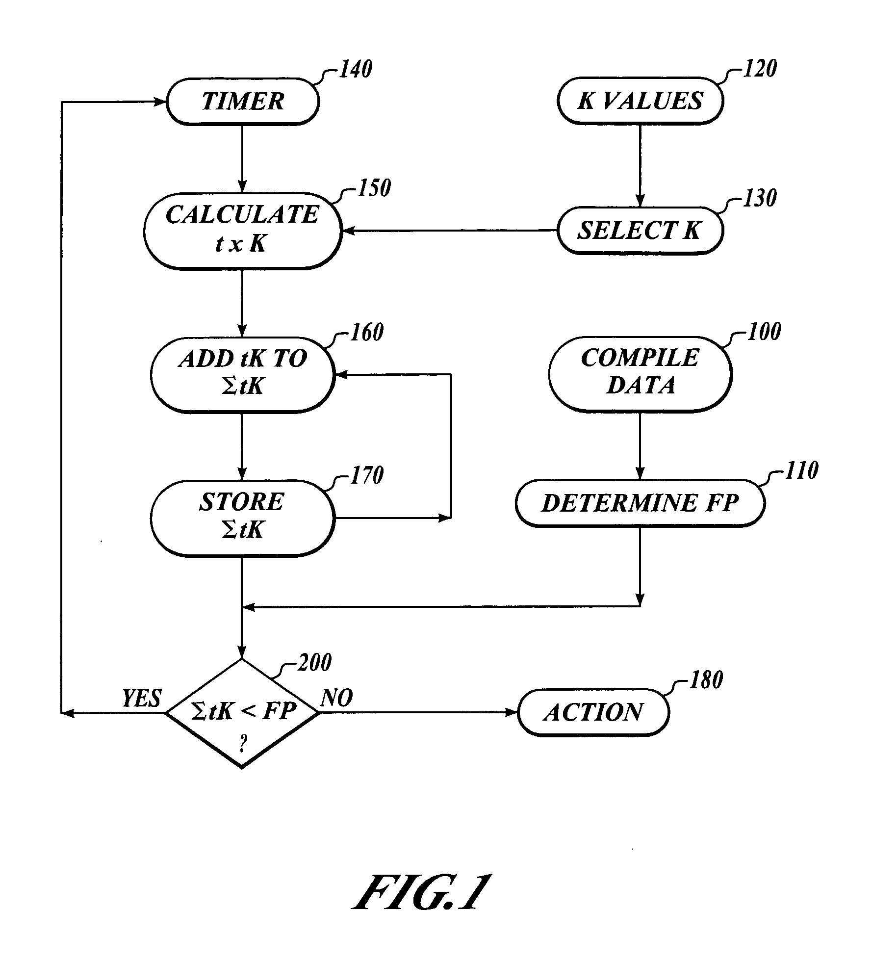
[0008] The invention provides a method, amenable to being programmed into a computer, that tracks varying “environmental factors” related to the severity of conditions to which product is exposed over a period of time to better estimate when a component of the product is about to fail. As a result, implementation of the invention provides a wide range of benefits. For example, in one aspect of the invention, manufacturers of products, for which the manufacturer usually provides a warranty of performance, are better able to estimate the number of failures that will likely occur over a period of time, including fluctuations in the number of failures that might be caused by factors such as high production rates, high usage, harsh environments during certain time periods, and the like. Further maintenance personnel using the invention would be better able to schedule preventive maintenance, potentially resulting in cost savings. In addition, for products that are made in large batches over short periods of time, and then stored for subsequent use, the invention provides a better method for determining when to take products out of storage for testing, and / or for determining what proportion will fail after elapse of time. In addition, implementation of the invention will permit the assessment of support costs of large populations of aircraft or other comparable complex systems over their entire intended existence before actual production even commences. This permits decision-makers more flexibility. For example, the decision-maker can account for support resources and costs very early in product development. The invention also permits decision-makers the option of choosing other subsystems that might require lower support costs but higher up front costs.
[0021] By taking into account environmental factors that have an effect on the life of a component of the product, the invention provides a better assessment of likely point of failure and permits better calculation of warranty liability, preventive maintenance intervals, or removal of the product from service or storage for disposal. The invention can be applied to a product as a whole, or subsystems of a product, or parts within any or all of the subsystems, as may be appropriate.

Problems solved by technology

In general, products that have multiple components fail in their intended purpose when a component necessary for the product to perform the function for that purpose fails.
By way of illustration, when an automobile, which has many components, has the mission of transporting a commuter to and from work suffers a failure of an electrical component that is necessary for the engine to operate, the automobile is stalled and unable to fulfill its mission.
In that case, the failure or burnout of the headlamps of the car makes it unsafe to use at night, and so it cannot fulfill a subsidiary, but nonetheless important, intended purpose.
Of course, the consumer product model explained above does not apply to all kinds of products.
For example, in the market for large commercial aircraft that carry hundreds of passengers, mission failure cannot be tolerated as readily as in the automotive industry.
There are also other areas where reliability of mission performance poses challenges.
Some industries have an added complication that their products have chemical, electronic and mechanical components or subsystems that are each prone to degradation with age, and mission performance reliability must be estimated in some manner.

Method used


Image

  • Lifecycle support software tool
  • Lifecycle support software tool
  • Lifecycle support software tool

Examples


example

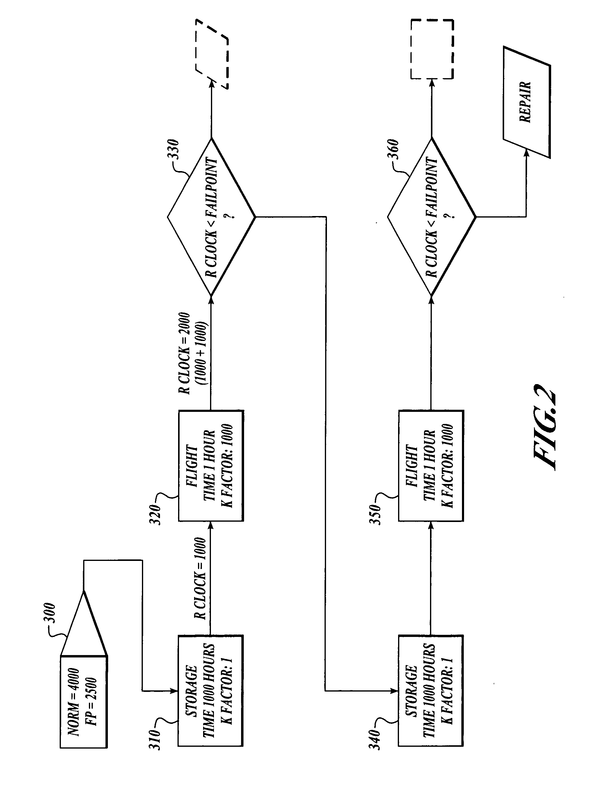
[0039] This example relates to an aircraft and is greatly simplified to illustrate an aspect of the invention. In this instance, the aircraft as a whole is the “component” to which aging factors are applied, depending upon the environment to which it is exposed.

[0040] In this example, in block 300, the MTBF (mean time between failures) was calculated as 4,000 hours, and a randomized fail point (FP) of 2,500 hours was determined for the aircraft using process simulation techniques. Thus a predicted failure for this particular aircraft is when the reliability clock, i.e. the sum of all [(K (aging factor) for environments to which it is exposed)×(time period of exposure)], is equal to 2,500.

[0041] In block 310 the aircraft is stored for 1,000 hours at an aging factor K=1.0; so the reliability clock is 1,000 after storage. Then, at block 320, the aircraft flies for 1.0 hour, at conditions with aging factor K=1,000. Thus, after block 320, the reliability clock is 1,000+(1.0×1,000)=2,00...


PUM


Abstract

The invention provides a simulation process and method of utilizing it to time to better estimate when a component of a product is about to fail by tracking varying “environmental factors” related to the severity of conditions to which product is exposed over a period of time. The invention includes the steps of: (a) determining a distribution of mean times between failures or failure rate for each component of the product; (b) using statistical techniques to select a fail point for each component; (c) applying an aging factor for each component for conditions to which the product is subjected; and (d) calculating an estimated time for failure for a component using information comprising time periods the component was subjected to conditions, and aging factors relating to the conditions.

Description

BACKGROUND OF THE INVENTION [0001] 1. Field of the Invention [0002] This invention relates to the field of software, and more particularly to software based simulation tools that use process simulation techniques to assess the performance reliability of products that are made up of multiple components, each component having a reliability distribution. [0003] 2. Description of the Related Art [0004] In general, products that have multiple components fail in their intended purpose when a component necessary for the product to perform the function for that purpose fails. By way of illustration, when an automobile, which has many components, has the mission of transporting a commuter to and from work suffers a failure of an electrical component that is necessary for the engine to operate, the automobile is stalled and unable to fulfill its mission. The auto might also serve other purposes, for example transporting people at night to social events. In that case, the failure or burnout of...

Claims


Application Information

Patent Timeline
IPC IPC(8): G06F15/00G06Q10/00
CPCG06Q10/06G06Q10/00
Inventor WILLIAMS, ZACHARY C.ADKINS, DUDLEY R.
Owner THE BOEING CO
Learn More