Loop-type thermosiphon and stirling refrigerator

a technology of thermosiphon and refrigerator, which is applied in the direction of refrigeration machines, domestic cooling apparatus, gas cycle refrigeration machines, etc., can solve the problems of less likely stability of circulation flow rate, no longer using cfc-based refrigerant, and fluctuation of temperature of heat source, etc., to achieve compact structure, promote separation of bubbles adhered to heat absorption portion or the like, and facilitate manufacturing

Inactive Publication Date: 2005-08-11
SHARP KK
View PDF15 Cites 34 Cited by
  • Summary
  • Abstract
  • Description
  • Claims
  • Application Information

AI Technical Summary

Benefits of technology

[0014] According to such an arrangement, the cooled and condensed working fluid is preheated after falling on the heat absorption portion instead of being directly supplied to the liquid pool, and thereafter it is supplied from above by gravitation. Accordingly, a flow is produced in the liquid pool and evaporation of the working fluid as a whole, including the working fluid in the liquid pool, is promoted. Naturally, evaporation of the working fluid that has been introduced and initially exchanges heat with the heat absorption portion is also promoted in an ensured manner, whereby temperature distribution in the high-temperature heat source can be uniform. In addition, separation of bubbles adhered to the heat absorption portion or the like can be promoted. Therefore, heat exchange adapted to fluctuation of the heat load can be performed, and the temperature of the high-temperature heat source can be stabilized. In addition, as the high-temperature heat source has a cylindrical shape and the evaporator has an annular shape, an apparatus having a compact structure and ensuring heat exchange efficiency can readily be manufactured.

Problems solved by technology

In the loop-type thermosiphon, however, circulation flow rate is less likely to be stabilized and a temperature of the heat source tends to fluctuate in many cases, depending on a type of a contained working fluid or heat load fluctuation in a certain range.
The CFC-based refrigerant, however, is no longer used, and the use of the HCFC-based refrigerant is restricted under the international treaty for protecting ozone layer.
Therefore, types of refrigerants that can be selected as a working fluid for the loop-type thermosiphon are limited from a viewpoint of environmental protection.
In the conventional loop-type thermosiphon, however, unstable circulation flow rate of the working fluid has been likely, resulting in fluctuation of the temperature of the heat source.
In particular, if the conventional loop-type thermosiphon is operated under a load far from a target load in accordance with design, the temperature of the heat source often fluctuates significantly.
If the temperature of the heat source fluctuates significantly, not only performance of heat source equipment becomes unstable, but also the heat source equipment may be damaged.
The loop-type thermosiphon often exhibits an unstable operation under fluctuating heat load.
If the temperature of the high-temperature portion is excessively high, a regenerator of the Stirling cooler may be destroyed.

Method used


Image

  • Loop-type thermosiphon and stirling refrigerator
  • Loop-type thermosiphon and stirling refrigerator
  • Loop-type thermosiphon and stirling refrigerator

Examples


first embodiment

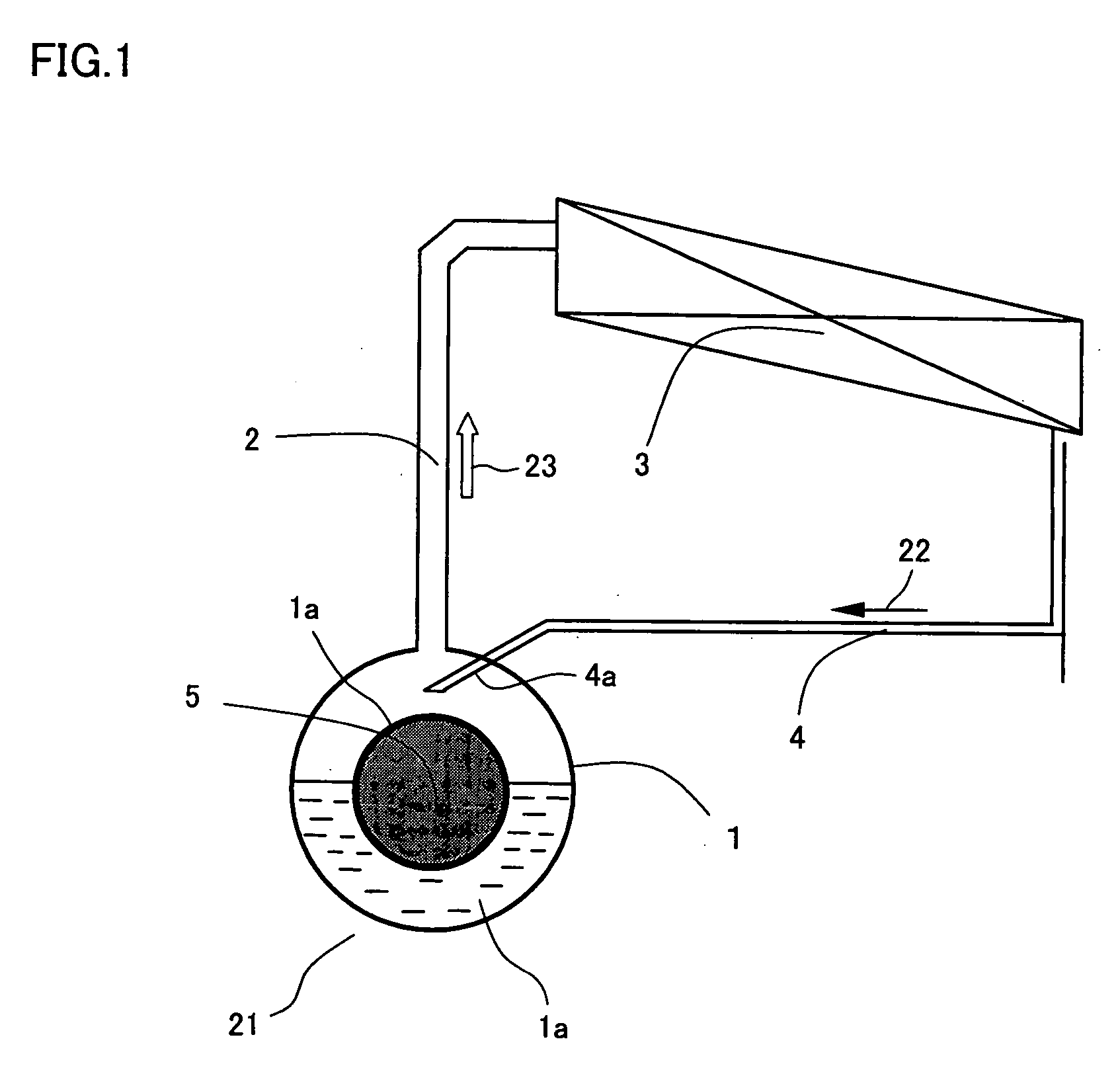
[0023]FIG. 1 is a conceptual diagram illustrating a basic arrangement of a loop-type thermosiphon in a first embodiment of the present invention. The loop-type thermosiphon shown in FIG. 1 is constituted of an evaporator 1, a condenser 3, a gas pipe 2 extending from evaporator 1 to condenser 3, and a liquid pipe 4 extending from condenser 3 to evaporator 1. In the present embodiment, as a high-temperature heat source 5 to be cooled has a cylindrical heat dissipation surface as shown in FIG. 1, the evaporator has an annular shape with a circular hole having a dimension adapted to the cylindrical heat dissipation surface of the heat source. In addition, a surface of the hole of the evaporator is brought in intimate contact with the cylindrical heat dissipation surface of heat source 5 in order to reduce thermal contact resistance. Condenser 3 is of a fin-tube type, and cools a working fluid flowing inside the pipe by flowing air around the same.

[0024] The pipe of the condenser for fl...

second embodiment

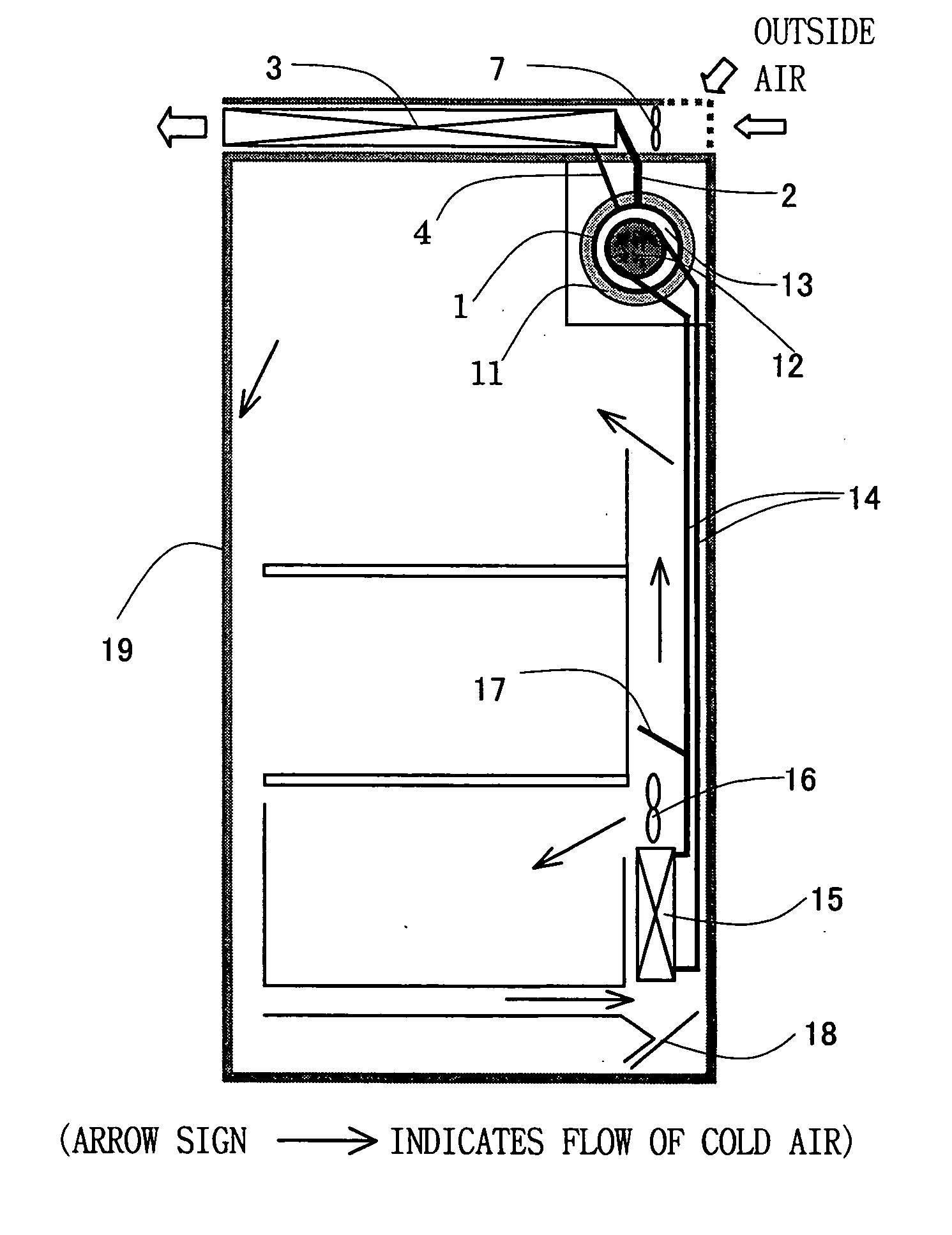
[0031]FIG. 3 is a conceptual diagram of a Stirling refrigerator according to a second embodiment of the present invention, provided with the loop-type thermosiphon. The Stirling refrigerator in FIG. 3 is constituted of a Stirling cooler provided in a refrigerator main body 19, the loop-type thermosiphon attached in order to cool a high-temperature portion of the Stirling cooler, a low-temperature side heat exchange system transferring a cold of a low-temperature portion of the Stirling cooler to the inside of the refrigerator, the refrigerator main body, and the like. Though the low-temperature side heat exchange system is implemented by the loop-type thermosiphon, it is the loop-type thermosiphon not of interest in the present embodiment.

[0032] A Stirling cooler 11 having cylindrical high-temperature and low-temperature portions is arranged on a back surface of the refrigerator. Evaporator 1 of the loop-type thermosiphon cooling a high-temperature portion 13 of the Stirling cooler...

third embodiment

[0037]FIG. 4 shows temperature fluctuation of the high-temperature heat source when a loop-type thermosiphon according to a third embodiment of the present invention is employed. The loop-type thermosiphon in the present embodiment is obtained merely by varying a manner of return of the liquid to the evaporator in the conventional loop-type thermosiphon shown in FIG. 6. In other words, the loop-type thermosiphon is structured such that the condensed working fluid is returned so as to contact with the heat absorption portion not being in contact with the liquid pool, instead of being directly introduced into the liquid pool.

[0038] The variation with time of the temperature of the high-temperature heat source shown in FIG. 4 exhibits an effect obtained under the condition of heat load the same as in the conventional loop-type thermosiphon. As compared with the large temperature fluctuation of the heat source in the conventional loop-type thermosiphon shown in FIG. 7, stable temperatu...


PUM


Abstract

A loop-type thermosiphon capable of stable operation regardless of fluctuation of heat load and a Stirling refrigerator using the same are provided. The loop-type thermosiphon transferring heat from a high-temperature heat source using a working fluid includes a evaporator having a heat absorption portion and evaporating the working fluid by depriving the high-temperature heat source of heat through the heat absorption portion, a condenser located above the high-temperature heat source and condensing the working fluid that has evaporated in the evaporator, and a pipe connecting the evaporator and the condenser so as to form a loop. In the loop-type thermosiphon, the working fluid that has passed through the condenser is brought in contact with the heat absorption portion before it is pooled in a liquid pool for the working fluid in the evaporator, so as to exchange heat with the same

Description

TECHNICAL FIELD [0001] The present invention relates to a loop-type thermosiphon and a Stirling refrigerator using the same. BACKGROUND ART [0002] A heat sink, a heat pipe, a thermosiphon, or the like is used for cooling a heat-generating instrument or a thermoelectric cooling device. As to the heat sink, temperature distribution is caused in a base portion thereof provided with a heat source. Accordingly, as a distance from the heat source is increased, the heat sink contributes less to heat dissipation. Meanwhile, the heat pipe or the thermosiphon has high heat transfer capability, and is characterized by small temperature variation even when the heat is transferred to a portion distant from the heat source. [0003] On the other hand, with regard to the heat pipe, vapor and liquid of a working fluid flows in the same pipe. As such, if an amount of heat transfer is large, a greater number of pipes are necessary. For example, if it is assumed that a temperature difference is set to 5...

Claims


Application Information

Patent Timeline
Patent Type & Authority Applications(United States)
IPC IPC(8): F25D11/00F25B1/00F25B9/14F25B23/00F25B25/00F25D23/00F28D15/02
CPCF25B9/14F25B23/006F25B25/005F28D15/0266F25D11/00F25D23/003F25B2309/06F28D15/02
Inventor ZHANG, HENGLIANGCHEN, WEIMASUDA, MASAAKI
Owner SHARP KK
Why Eureka
Try Eureka