Isolated capacitive fluid level sensor

a capacitive, fluid level sensor technology, applied in liquid/fluent solid measurement, instruments, machines/engines, etc., can solve the problems of corrosion and electrical conductivity, and achieve the effect of reliable separation of sensing elements, low cost and easy addition

Inactive Publication Date: 2005-08-11
NYCE DAVID SCOTT
View PDF5 Cites 75 Cited by
  • Summary
  • Abstract
  • Description
  • Claims
  • Application Information

AI Technical Summary

Benefits of technology

[0011] Both the prior art level sensors and the present invention provide for the measurement of the level of a fluid contained within a vessel, without using a float. It is an object of the present invention, in contrast to prior art fluid level sensors, to provide a novel method for measuring fluid level in a vessel with an isolated sensing element, the vessel having at least a portion of at least one wall made of a dielectric material. The novel method avoids the problems associated with immersion of a sensing element into the measured fluid or the complexity of producing a slowed electromagnetic wave. The present invention provides long-term reliability due to the absence of contact with the measured fluid. In the case where the measured fluid is corrosive, the vessel would normally be constructed of a compatible material according to standard practice in the art. The vessel wall can therefore provide reliable separation of the sensing element from a corrosive measured fluid contained within the vessel. In the case of an electrically conductive measured fluid, this same construction prevents measurement errors that may be due to conduction between the sensing element conductors and through the measured fluid, since the present invention teaches the use of a dielectric wall separating the sensor from the conductive fluid. A sensor made according to a first embodiment of the present invention can be easily added to a vessel that is already mounted in place. This is accomplished by mounting the sensing element onto the outside of a dielectric wall of the vessel. Alternatively, the sensing element may be embedded within a dielectric wall of the vessel. A sensor made according to a second embodiment of the present invention can be fabricated at exceptionally low cost by

Problems solved by technology

Even when an immersed sensor is anodized as taught in the prior art (U.S. Pat. No. 6,564,658), or otherwise coated with a compatible material, corrosion

Method used


Image

  • Isolated capacitive fluid level sensor
  • Isolated capacitive fluid level sensor
  • Isolated capacitive fluid level sensor

Examples


Embodiment Construction

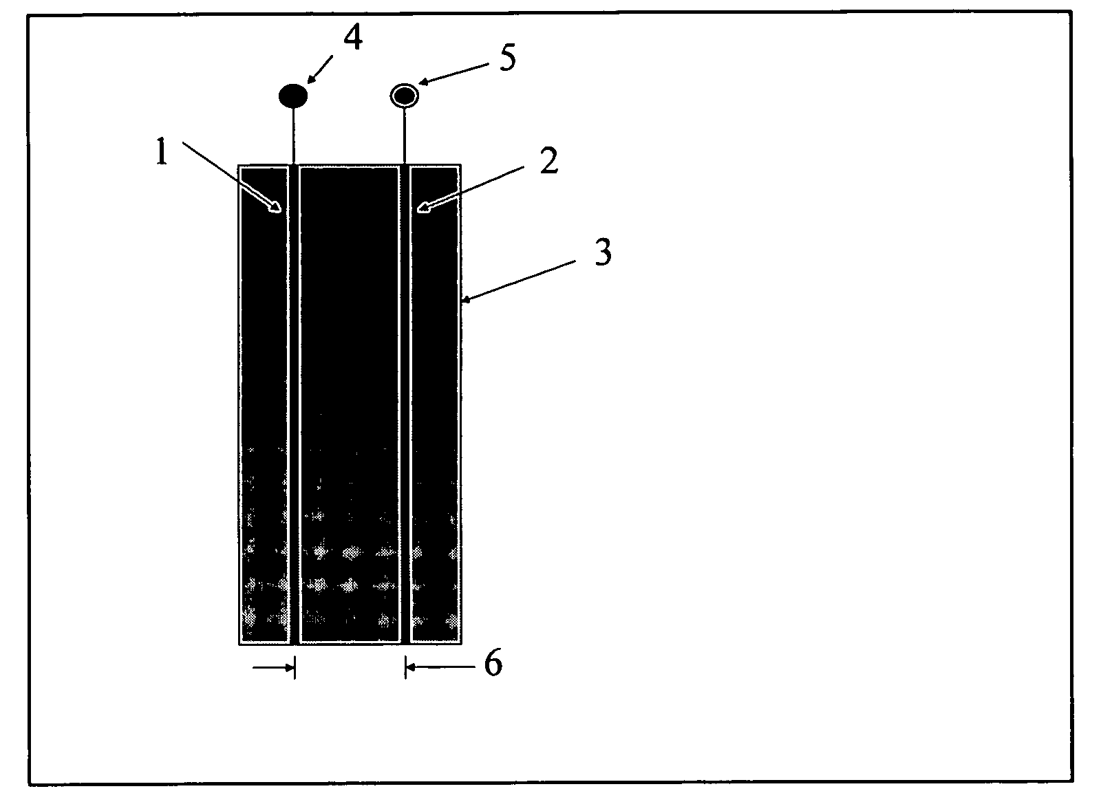
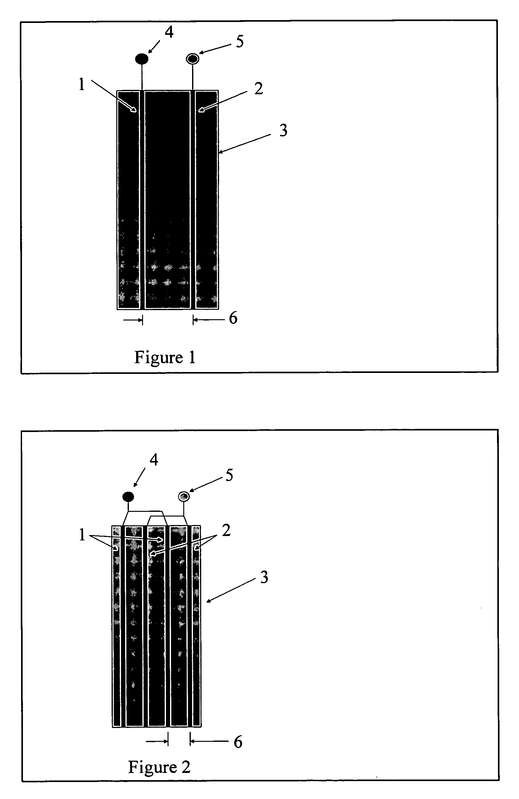
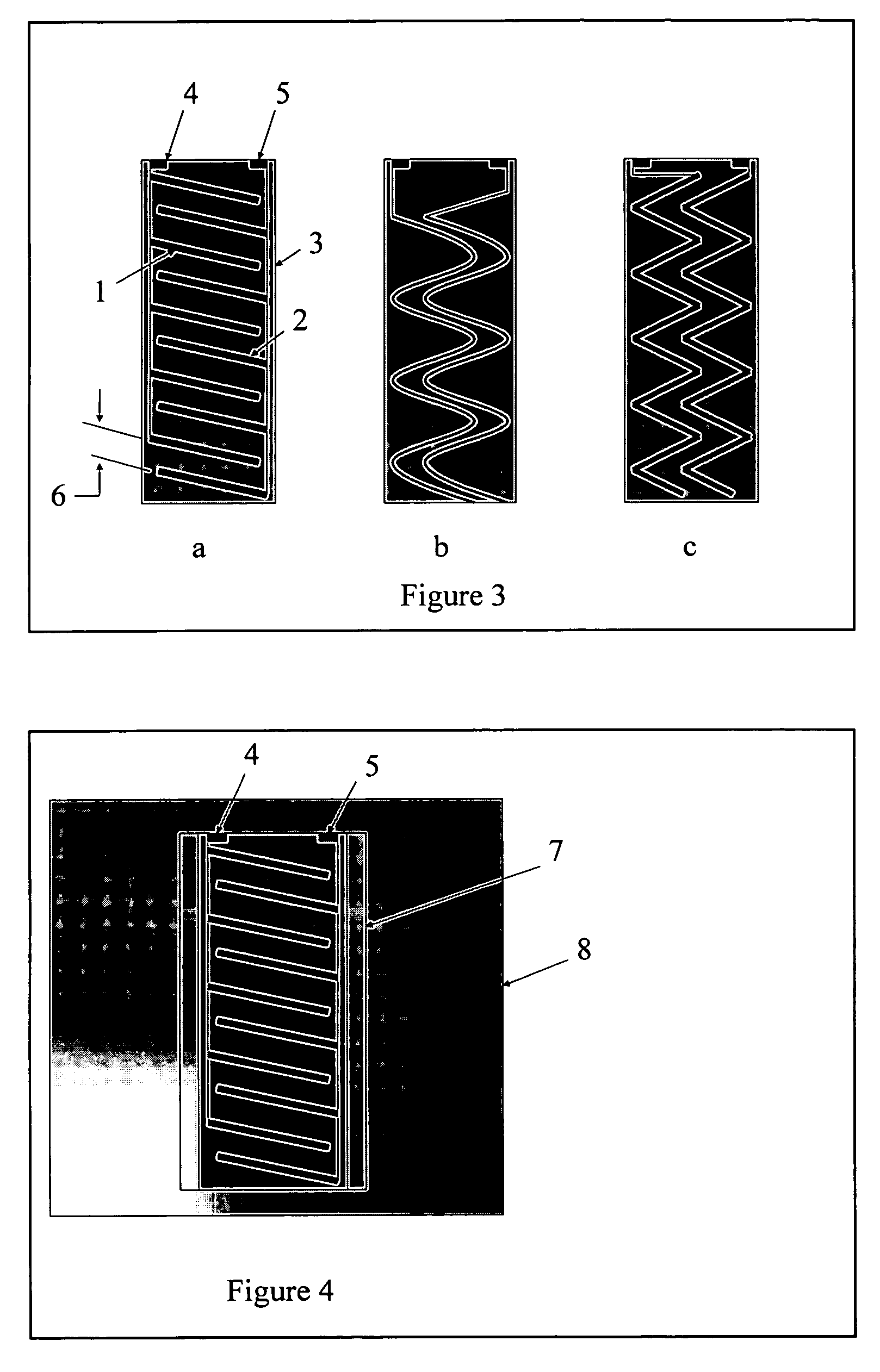
[0027] A first preferred embodiment of the present invention enables the measurement of fluid level when the fluid is contained within a vessel that has at least one wall made of a dielectric material. An application of a fluid level sensor of the first preferred embodiment is shown in FIG. 6, and described more fully in a subsequent paragraph. Vessel 9 may be a marine holding tank, designed to hold waste water until an appropriate time for discharge. Level information is helpful in order to discharge the waste water at an appropriate time and location. Configuration of a capacitive sensing element according to the present invention provides the advantage of separation of the sensing element from a corrosive waste fluid. A sensing element is used that can take any of several forms, depending on the requirements of the application. A version of a sensing element of the first preferred embodiment is shown in FIG. 1. A set of electrically conductive electrodes 1 and 2, comprise the sen...


PUM


Abstract

A capacitive fluid level sensor is disclosed that operates without the use of a float, wherein sensing electrodes are spaced to form a measured capacitance that changes in accordance with a changing fluid level, the electrodes forming a sensing element, and being electrically insulated from the measured fluid. The sensing element is fabricated such that it can be attached to the outside of a dielectric wall of a vessel, or embedded within a dielectric material. An interdigital comb configuration of sensing element is also disclosed in which depressions or gaps are formed into a dielectric material that is present between the fingers of the comb.

Description

BACKGROUND OF THE INVENTION [0001] 1. Field of the Invention [0002] The present invention relates to sensors for measurement of fluid level. The measured fluid may be contained in a sump, reservoir, process vessel, holding tank, or other man made or natural fluid container. A fluid container is herein called the vessel. An example of such a vessel is a holding tank for a marine use. At least a part of at least one vessel wall is fabricated from an electrically non-conductive material. The terms electrically non-conductive, insulating, and dielectric are used here interchangeably. [0003] More particularly, the present invention relates to a capacitive level sensor that measures fluid level in the vessel without the use of a float, and functions based on the permittivity of the measured fluid being substantially different from that of air, the sensing element of the capacitance level sensor being electrically insulated from the measured fluid. [0004] The capacitive level sensor of the...

Claims


Application Information

Patent Timeline
IPC IPC(8): G01F23/26
CPCG01F23/268G01F23/263
Inventor NYCE, DAVID SCOTT
Owner NYCE DAVID SCOTT
Why Eureka
Try Eureka