Electromagnetic wave shield gasket and its manufacturing method

a technology of electromagnetic shield and manufacturing method, which is applied in the direction of conductive layers on insulating supports, instruments, synthetic resin layered products, etc., can solve the problems of material loss of intrinsic resiliency, high cost of conductive sheets containing metal powder, and extremely difficult to form

Inactive Publication Date: 2005-08-11
ZIPPERTUBING (JAPAN) LTD
View PDF7 Cites 8 Cited by
  • Summary
  • Abstract
  • Description
  • Claims
  • Application Information

AI Technical Summary

Benefits of technology

[0029] Using the manufacturing method above, an electromagnetic wave shield gasket having the exce

Problems solved by technology

Hei 11-220283, a conductive sheet containing metal powder is generally expensive and the material may lose its intrinsic resiliency (cushioning property) when filled with a conductive material.
When an attempt is made to produce an extremely thin electromagnetic wave shield gasket, the gasket, which consists of a sponge-like foam with a wound conductive film or filament is extremely difficult to form because of reduced core rigidity, which problematically reduces production efficiency.
Furthermore, sponge tailings, fabric fuzz, and filament fragments are generated from the materials and plated metal flakes from the plated items, possible causes of short-circuiting in a mountable electronic device.
Non-woven fabric is made conductive and used as a cushioning material for the gasket body, causing

Method used


Image

  • Electromagnetic wave shield gasket and its manufacturing method
  • Electromagnetic wave shield gasket and its manufacturing method
  • Electromagnetic wave shield gasket and its manufacturing method

Examples


embodiment 1

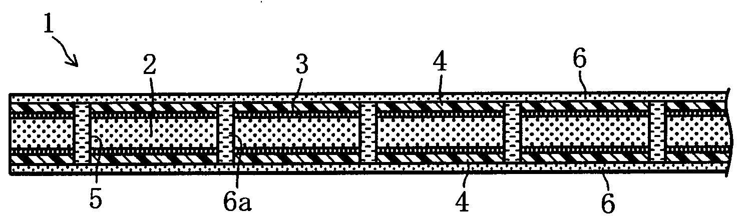
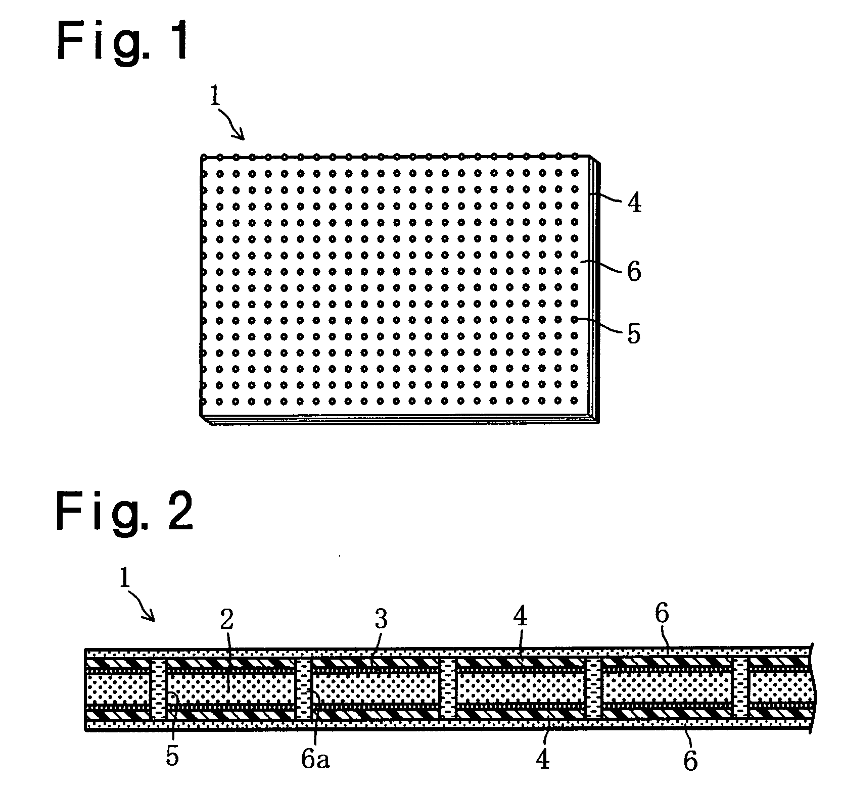
[0041] As shown in FIGS. 1 and 2, an electromagnetic wave shield gasket sheet 1 of Embodiment 1 comprises a synthetic resin foam sheet 2 having open or closed cells (continuous or independent cells), flexible synthetic resin films 4, 4 bonded to the foam sheet 2 on both sides using an adhesive material 3, numerous through-holes 5 formed through the thickness of the foam sheet 2 and films 4 on both sides, conductive layers 6, 6 (conductive coatings) formed on the surfaces of the films 4, 4 on both sides, and numerous conductive passages 6a formed in the numerous through-holes 5 and electrically connected to the conductive layers 6, 6 on both sides.

[0042] As shown in FIGS. 1 and 2, the numerous through-holes 5 are formed through the thickness of the front-side synthetic resin film 4, foam sheet 2, and back-side synthetic resin film 4. The conductive layers 6 are formed on the surfaces of the films 4, 4 on both sides. The through-holes 5 are filled with the same conductive material as...

embodiment 2

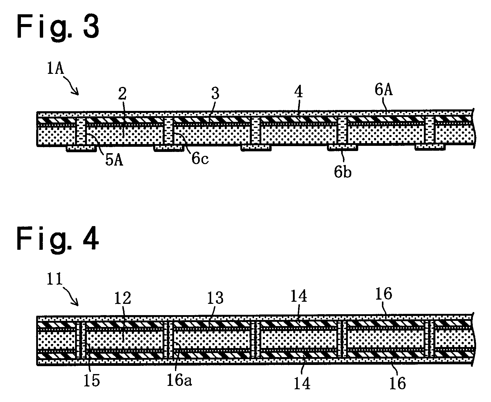
[0060]FIG. 3 shows an electromagnetic wave shield gasket 1A, according to Embodiment 2, in which the same components are given the same reference numerals as in the electromagnetic wave shield gasket 1 of the embodiment described above. The electromagnetic wave shield gasket 1A has a similar perspective view to that of FIG. 1.

[0061] The electromagnetic wave shield gasket 1A comprises a resilient synthetic resin foam sheet 2 having open or closed cells, a flexible synthetic resin film 4 bonded to the foam sheet 2 on one side using an adhesive 3, numerous through-holes 5 formed through the thickness of the foam sheet 2 and film 4, a conductive layer 6A (conductive coating) formed on the surface of the synthetic resin film 4, numerous conductive coating segments 6b formed near the openings of the multiple through-holes 5A on the side of the foam sheet 2 where there is no film 4, and multiple conductive passages 6c formed in the numerous through-holes 5A and electrically connecting the...

embodiment 3

[0072]FIG. 4 shows an electromagnetic wave shied gasket sheet 11 according to Embodiment 3. The electromagnetic wave shied gasket sheet 11 has a similar perspective view to FIG. 1.

[0073] The electromagnetic wave shield gasket sheet 11 comprises a resilient synthetic resin foam sheet 12 having open or closed cells, flexible synthetic resin films 14, 14 bonded to the foam sheet 12 on both sides using an adhesive material 13, numerous through-holes 15 formed through the thickness of the foam sheet 12 and films 14, 14 conductive layers (conductive coatings) 16, 16 formed on the surfaces of both films 14, 14 and numerous conductive passages 16a formed in the numerous through-holes 5 and electrically connecting both of the conductive layers 16, 16.

[0074] The synthetic resin foam sheet 12 is made by slicing a resilient foam block. The synthetic resin foam sheet 12 is made of a synthetic resin or a synthetic or natural rubber, which is selected from, for example, urethane resin, ethylene ...


PUM

PropertyMeasurementUnit
Thicknessaaaaaaaaaa
Diameteraaaaaaaaaa
Fractionaaaaaaaaaa

Abstract

Synthetic resin films 4, 4 are bonded to a thin foam sheet 2 on both sides. Numerous through-holes 5 are formed in the laminated sheet from the front to back side. A conductive coating material is applied to the surfaces of the films 4, 4 and fill the numerous through-holes 5 to form conductive layers 6, 6 on the surfaces of the films 4, 4 and numerous conductive passages 6a in the numerous through-holes 5 connected to conductive layers 6, 6. In another structure, a film and a conductive layer are formed on one side of the foam sheet, numerous conductive coating segments are formed near the openings of numerous through-holes on the back, and the conductive layer and numerous conductive coating segments are connected via numerous conductive passages.

Description

TECHNICAL FIELD [0001] The present invention relates to an electromagnetic wave shield gasket for shielding electromagnetic waves generated in electronic devices and measuring instruments or undesired electromagnetic waves invading from the outside and its manufacturing method. [0002] A variety of electromagnetic wave shield gaskets are provided on the housings of electronic devices and measuring instruments that generate electromagnetic waves and medical equipment. Such shield gaskets are often of a sheet type for space-saving as a result of the down-sized and light-weight design of electronic devices. [0003] Prior art electromagnetic wave shield gasket sheets include a conductive sheet containing metal powders, a thin sponge-like foam with a conductive film or conductive filaments wound for electrical conductivity, the electro-less plated urethane foam described in Japanese Laid Open Patent Application Publication No. Hei 11-214886, and a porous synthetic resin sheet having woven ...

Claims


Application Information

Patent Timeline
IPC IPC(8): B32B27/18G12B17/02H01B5/14H05K9/00
CPCH05K9/0015H05K9/00
Inventor OHTSUKA, HIRAAKISAITO, HARUKABABA, MOTOYASUMATSUOKA, SHIGEKI
Owner ZIPPERTUBING (JAPAN) LTD
Why Eureka
Try Eureka