Energy storage method for load hoisting machinery

a technology of energy storage and hoisting machinery, which is applied in the direction of motor/generator/converter stopper, dynamo-electric converter control, elevator, etc., can solve the problems of short battery life, inability to achieve energy storage in a viable way, and inability to demonstrate the satisfactory performance of dc motor-driven flywheel, so as to reduce the overall power requirements of operation

Active Publication Date: 2005-08-11
PACECO
View PDF7 Cites 31 Cited by
  • Summary
  • Abstract
  • Description
  • Claims
  • Application Information

AI Technical Summary

Benefits of technology

[0018] It is therefore an important object of the present invention to provide an improved method for energy storage for the operation of induction motor-driven hoist machinery to reduce the overall power requirements for the operation of the machinery.
[0019] It is another object of the present invention to provide an improved method for energy storage for the operation of induction motor-driven hoist machinery to average out the power consumption requirements of the machinery.
[0020] It is a further object of the present invention to provide a method for the operation of induction motor-driven hoist machinery that eliminates the need to send power back to the source when the motor is driven by lowering the load or to absorb the power in a resistor or a brake.

Problems solved by technology

However, until now, the practical aspects of the query have prevented its use.
However, in reality, the battery component imposes numerous problems such as: small electrical capacity, electrical inefficiency, large physical battery volume, heavy weight, and short battery life, whereby such a system is not currently a viable way to accomplish energy storage utilizing even state-of-the-art battery technology.
In order to transmit the energy to the flywheel at the variable speeds, a DC motor has been utilized as most suitable, but the DC motor-driven flywheel has not been proven satisfactory for numerous reasons among which the following are most limiting:
However, the DC motor which must be interconnected to the flywheel has severe rotational speed limitations due to the weak centrifugal strength of its rotor's coil component;
A DC motor is comparatively large, heavy, and expensive.
For these reasons and others, the flywheel-driven energy storage type system utilizing a DC motor has likewise not been a viable way to accomplish the result.
However, since the reverse power current includes surge and deviant frequencies, other consumers dislike receiving it.

Method used


Image

  • Energy storage method for load hoisting machinery
  • Energy storage method for load hoisting machinery
  • Energy storage method for load hoisting machinery

Examples


Embodiment Construction

[0034] Reference is made to the drawings for a description of the preferred embodiment of the present invention wherein like reference numbers represent like elements on corresponding views.

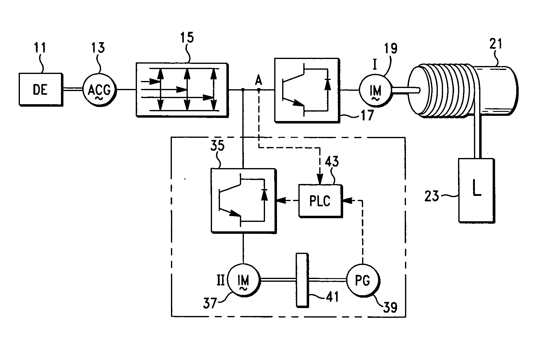
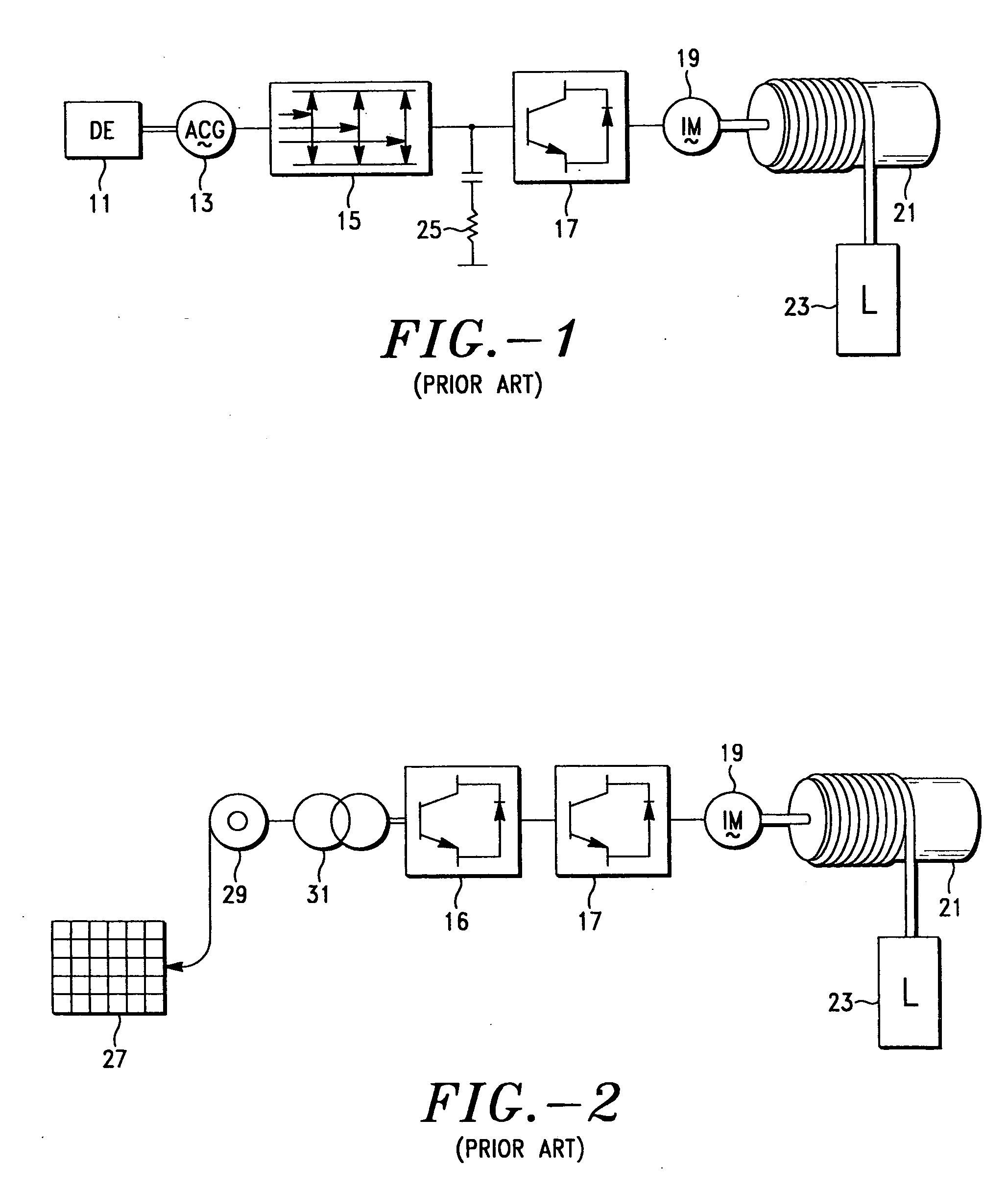
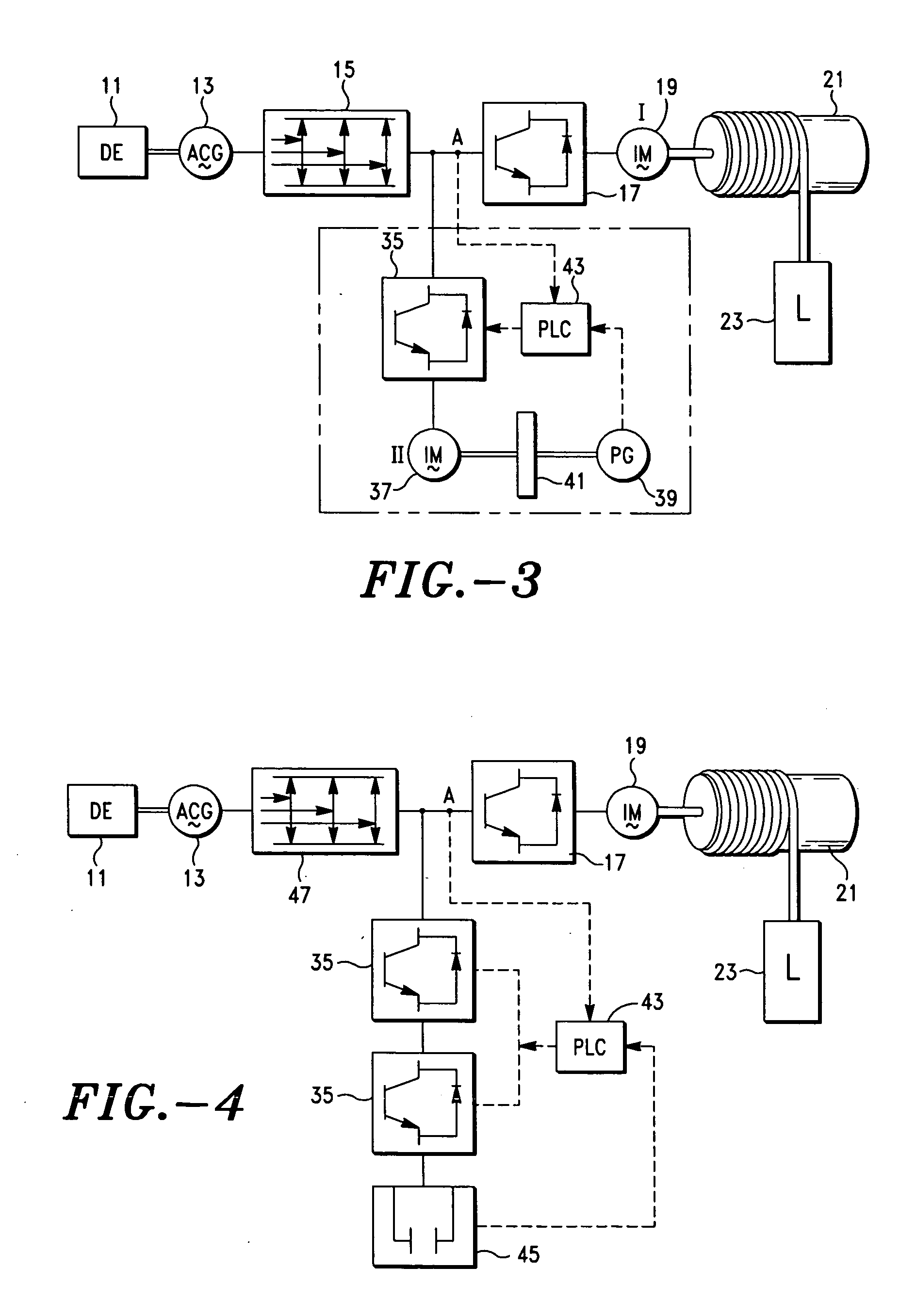
[0035]FIGS. 1-3 show the prior art of present practices as described above in the DESCRIPTION OF THE PRIOR ART portion of this specification. FIG. 3 shows the prior art patented apparatus which modifies the apparatus of FIG. 1 by the additions shown within the broken lines. The description of FIG. 1 in the DESCRIPTION OF THE PRIOR ART describes the operation of the primary apparatus items 11, 13, 15, 17, 19, 21 and 23.

[0036] Reference is made to FIG. 3 for a description of the environment of the present invention. When a load 23 is raised by the hoist machinery 21 of the system, in both the prior art and the present invention, electrical energy from either a municipal utility power grid or from an autonomous diesel engine powered generator 13 is utilized to operate a first induction motor 19 wh...


PUM


Abstract

A method for energy storage and recovery for load hoisting equipment powered by an induction hoist motor controlled by a first inverter and having a dual inverter controlling a capacitor utilizing rest power such as reverse power generated from the motor when lowering a load, and unused power at small load or idle, to charge the capacitor whereby energy is stored in the capacitor and the system is reversed when a load is lifted and power is consumed whereby the capacitor is discharged to deliver power to the hoist motor.

Description

BACKGROUND OF THE INVENTION [0001] 1. Field of the Invention [0002] The present invention relates to improvements in a patented energy storage method for use with cranes and other load hoisting machinery. More particularly, it relates to improvements in a method for storing energy in a capacitor which is charged by the load hoisting machinery drive motor. The stored energy is resupplied to the system when the load is being raised and needs more power. [0003] 2. Description of the Prior Art [0004] The present invention relates to improvements in a system or method for energy storage in load hoisting cranes which are driven by electrical power. It is particularly useful for machinery which is driven by diesel-electric generators that experience a wide range of varying loads. The system stores energy at reverse or small load and supplies power at peak or large loads. Theoretically, this is a simple mechanical query, having as a result the benefit that the primary electrical source is o...

Claims


Application Information

Patent Timeline
Patent Type & Authority Applications(United States)
IPC IPC(8): B66B1/00B66B1/30H02P3/14
CPCB66B1/30Y02B50/142B66C13/28Y02B50/00H02J7/04
Inventor TAKEHARA, TORUICHIMURA, KINYA
Owner PACECO
Why Eureka
Try Eureka