Wavefront aberration compensation element, optical pickup, and optical disk apparatus

a compensation element and wavefront aberration technology, applied in the direction of data recording, optical recording heads, instruments, etc., can solve the problems of spot diameter not being reduced, and recording/reproduction/erasing cannot be suitably performed

Inactive Publication Date: 2005-08-11
RICOH KK
View PDF8 Cites 21 Cited by
  • Summary
  • Abstract
  • Description
  • Claims
  • Application Information

AI Technical Summary

Benefits of technology

[0031] In the optical pickup according to an embodiment of the present invention, the liquid crystal layer of the wavefront aberration compensation element may compensate for a spherical aberration with respect to the luminous flux with the long wavelength being incident on the objective lens.

Problems solved by technology

Therefore, recording / reproduction / erasing cannot be suitably performed.
However, the wavefront aberration shown in FIG. 10 is a large wavefront aberration of 0.7 λ. With such an optical pickup, the spot diameter cannot be reduced, and recording / reproduction / erasing cannot be suitably performed.
However, since the pupil diameter is constant, minutely defining the levels narrows the width of each level and causes difficulty in manufacturing (processing).
In addition, with such an optical element being manufactured mainly with glass or molded plastic, the refractive index is drastically changed by wavelength changes due to fluctuations in wavelengths and changes in atmospheric temperature, and changes in wavefront aberrations (chromatic aberrations) are caused by phase difference.
Furthermore, with such a phase conversion element, newly created wavefront aberrations due to axial deviation between the phase conversion element and the optical system cannot be compensated for.
Considering that the refractive index is 0.2 to 0.25, and that the power source of the optical pickup is mainly 5V, the wavefront aberration compensation of the liquid crystal element has a limit of 1 λ. That is, the compensation for the wavefront aberration using the liquid crystal element is unsuitable for large aberrations.
However, since the divergent point of the DVD is fixed, the layout of the optical system is restricted.
Furthermore, a residual aberration is caused from differences in magnification of the optical system, and the rms value of 0.07 λ or less cannot be obtained.

Method used


Image

  • Wavefront aberration compensation element, optical pickup, and optical disk apparatus
  • Wavefront aberration compensation element, optical pickup, and optical disk apparatus
  • Wavefront aberration compensation element, optical pickup, and optical disk apparatus

Examples


Embodiment Construction

[0054] In the following, embodiments of the present invention are described with reference to the accompanying drawings.

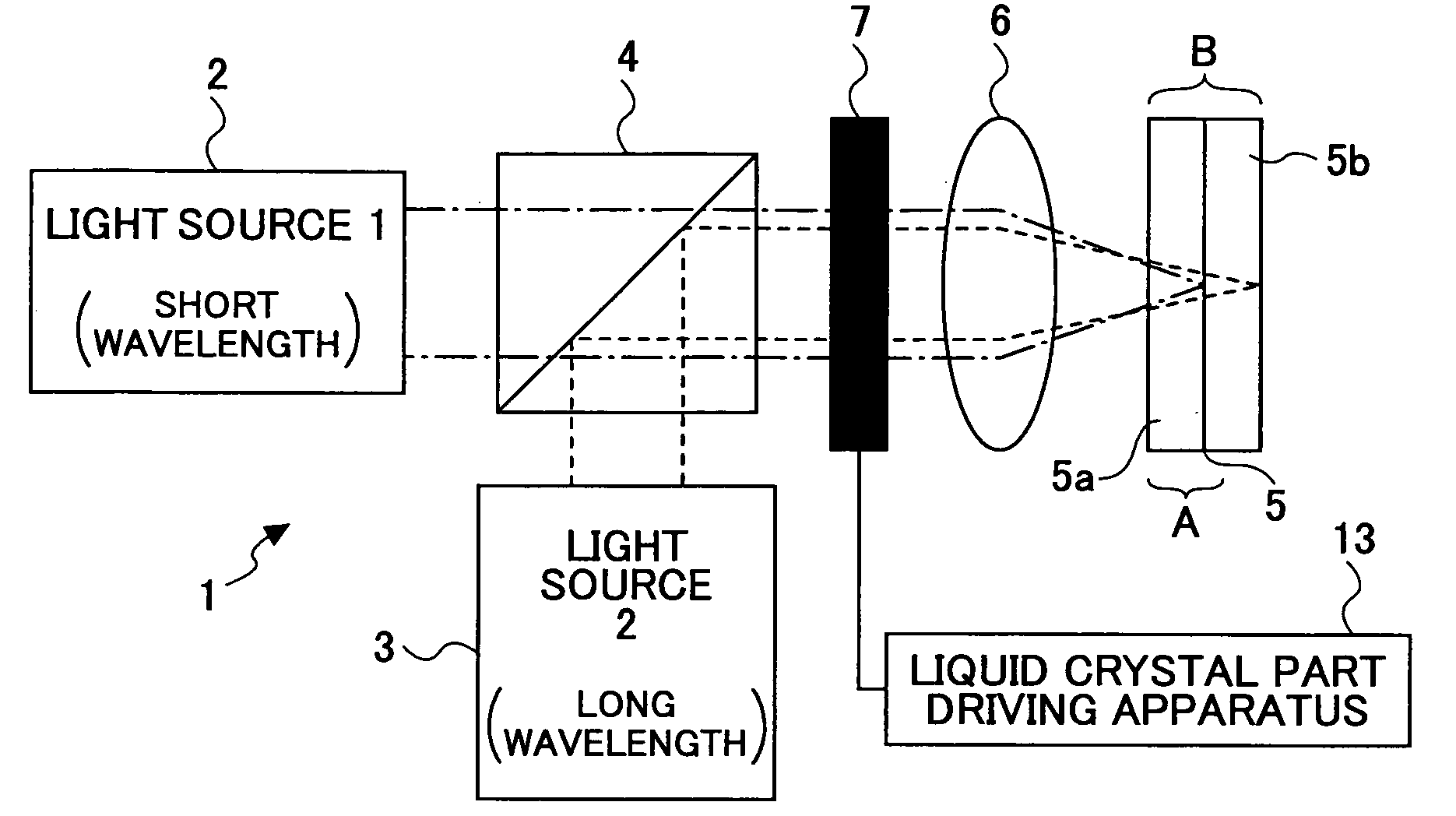
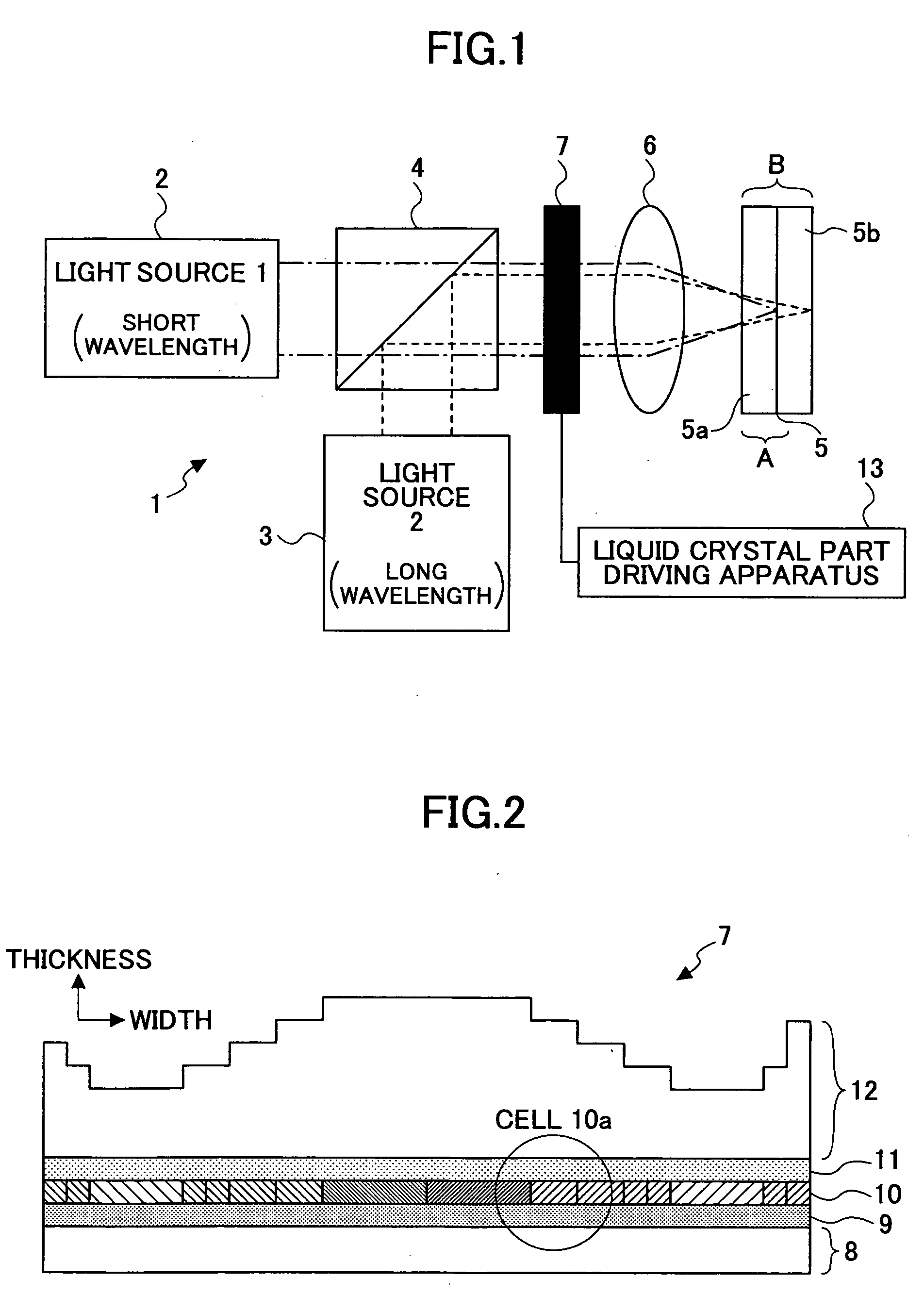
[0055]FIG. 1 is a schematic diagram showing a basic structure of an optical pickup 1 of an optical disk apparatus according to an embodiment of the present invention. The optical pickup 1 has a light source 2 for emitting a luminous flux (bundle of rays) of a relatively short wavelength, a light source 3 for emitting a luminous flux of a relatively long wavelength, and a wavelength combining prism 4 for combining the bundles of rays emitted from the light sources 2 and 3 into the same optical path. A common objective lens 6 for converging the bundles of rays onto an information recording medium 5 is disposed on the optical path. In the bundle of rays converged by the objective lens 6, the bundle of rays from the light source 2 forms a beam spot on a surface of an information recording medium part 5a having a substrate thickness A, and the bundle of rays from the l...


PUM

PropertyMeasurementUnit
thicknessaaaaaaaaaa
thicknessaaaaaaaaaa
wavelengthaaaaaaaaaa

Abstract

A wavefront aberration compensation element includes a wavelength selection phase plate having a plurality of phase steps having various thicknesses at various areas, a liquid crystal layer for obtaining a prescribed wavefront aberration, and a pair of first and second electrode layers having the liquid crystal layer disposed therebetween, wherein either one of the wavelength selection phase plate and the pair of first and second electrode layers having the liquid crystal layer disposed therebetween is stacked on the other.

Description

BACKGROUND OF THE INVENTION [0001] 1. Field of the Invention [0002] This invention relates to a wavefront aberration compensation element, an optical pickup, and an optical disk apparatus for accommodating light sources of various wavelengths. [0003] 2. Description of the Related Art [0004] An optical disk apparatus records information on a recording surface of an optical disk with spiral or concentric tracks formed thereto, and performs operations of recording / reproduction / erasing information based on the light directed to and reflected from the recording surface of the optical disk. [0005] Typically, an optical system of an optical pickup includes a light source 101 and an objective lens 102 as shown in a schematic diagram of FIG. 9. In order to control the fine spot on an information recording medium 103, the optical system of the optical pickup is provided with a lens actuator 104 for executing focus and track control of the objective lens 102. Numeral 105 is a detection / separat...

Claims


Application Information

Patent Timeline
Patent Type & Authority Applications(United States)
IPC IPC(8): G11B7/00G11B7/135
CPCG11B7/1367G11B2007/0006G11B7/13925G11B7/1369
Inventor OGATA, TETSUYA
Owner RICOH KK
Why Eureka
Try Eureka