Self-descriptive microphone array

a microphone array and self-description technology, applied in the direction of transducer details, electrical transducers, electrical apparatus, etc., can solve the problems of increasing array costs, aec typically fails, and sub-optimal supply, so as to reduce the cost of microphone arrays and manufacture. the effect of cost reduction

Active Publication Date: 2005-08-11
MICROSOFT TECH LICENSING LLC
View PDF6 Cites 105 Cited by
  • Summary
  • Abstract
  • Description
  • Claims
  • Application Information

AI Technical Summary

Benefits of technology

[0015] Consequently, because the self-descriptive microphone array makes use of external computing power, rather than including onboard audio processing hardware and software, the self-descriptive microphone array is relatively inexpensive to manufacture in comparison to conventional microphone array devices that include onboard audio processing capabilities. Further, because external processing power is used for audio processing, combined applications such as, for example, adaptive beamforming combined with acoustic echo cancellatio...

Problems solved by technology

Consequently, when external software applications attempt to provide AEC processing in a remote computing device, such as a PC-type computer, while performing beamforming computations within the microphone array itself, the AEC typically fails, or provides sub-optimal results.
Therefore, such arrays must typically include additional onboard processing capabilities, thereby increasing array expense, in order to perform adaptive beamforming processing in combination with AEC processing.
Unfortunately, such onboard hardware tends to be significantly more expensive than the actual microphones in the array.
Further, because the hardware and software is typically included within the array, updating the hardware and software is often difficult or impossible for an end-user of the ...

Method used


Image

  • Self-descriptive microphone array
  • Self-descriptive microphone array
  • Self-descriptive microphone array

Examples


Embodiment Construction

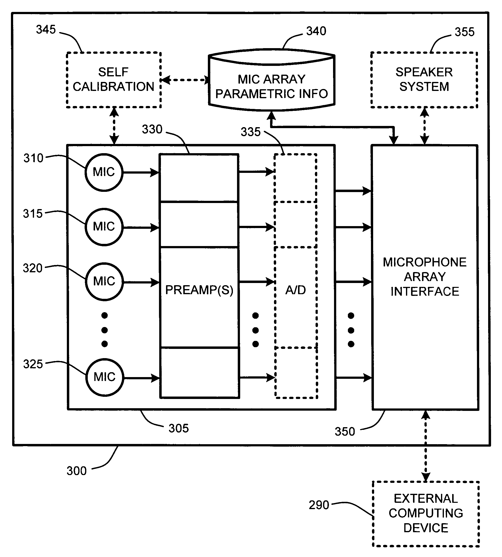
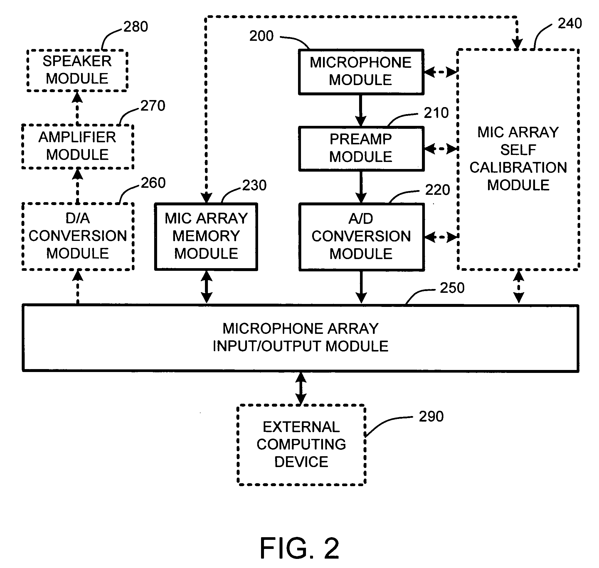
[0028] In the following description of the preferred embodiments of the present invention, reference is made to the accompanying drawings, which form a part hereof, and in which is shown by way of illustration specific embodiments in which the invention may be practiced. It is understood that other embodiments may be utilized and structural changes may be made without departing from the scope of the present invention.

1.0 Exemplary Operating Environment:

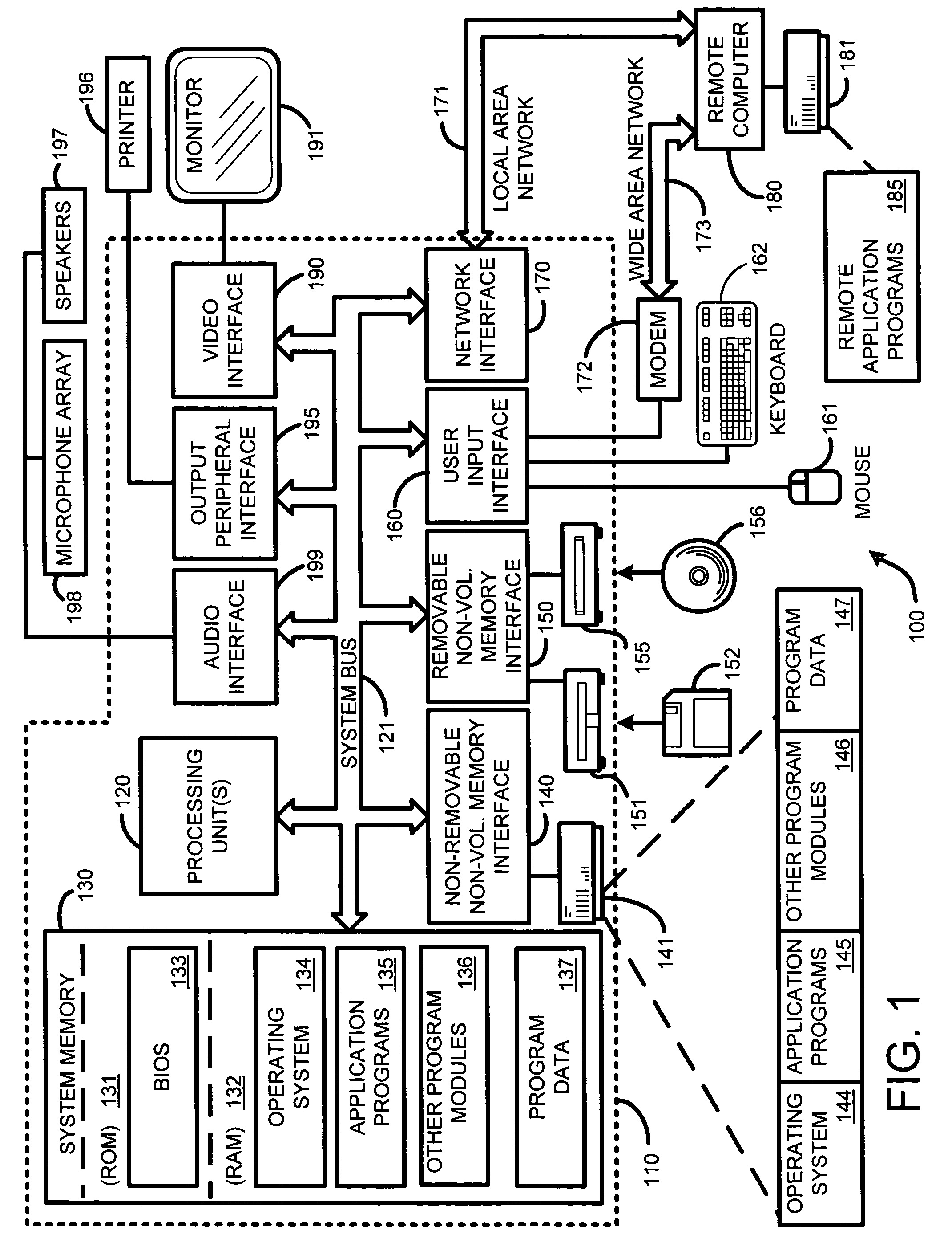
[0029]FIG. 1 illustrates an example of a suitable computing system environment 100 on which the invention may be implemented. The computing system environment 100 is only one example of a suitable computing environment and is not intended to suggest any limitation as to the scope of use or functionality of the invention. Neither should the computing environment 100 be interpreted as having any dependency or requirement relating to any one or combination of components illustrated in the exemplary operating environment 100.

[0030] Th...


PUM


Abstract

A self-descriptive microphone array includes a microphone array memory, such as, for example a ROM, EEPROM, or other conventional memory, which contains a microphone array device description. This device description includes parametric information which defines operational characteristics and configuration of the microphone array. In further embodiments, the microphone array uses any of a variety of conventional wired or wireless computer interfaces, including serial, IEEE 1394, USB, Bluetooth™, etc., to connect to a computing device. Once connected, the microphone array provides its device description to the computing device. Sound processing software residing within the computing device is then automatically configured for optimally interacting with one or more analog or digital audio signals provided by the microphone array. In another embodiment, the microphone array performs integrated self calibration for automatically updating the device description. The self calibration is performed either upon connection to the computing device, or upon regular or user-specified intervals.

Description

BACKGROUND [0001] 1. Technical Field [0002] The invention is related to a microphone array having one or more microphones in a predetermined arrangement, and in particular, to a self-descriptive microphone array that automatically self-calibrates and provides a current configuration and state to a computer to which it is connected, so that the computer can automatically configure audio processing software to be used for processing audio signals captured via the microphone array. [0003] 2. Related Art [0004] Conventional microphone array type devices are well known to those skilled in the art. In general, microphone arrays typically include an arrangement of microphones in some predetermined layout. These microphones are generally used to capture sounds from various directions and originating from different points in space. Once captured, onboard sound processing software and hardware then provides sound processing capabilities, such as, for example, sound source localization, beam f...

Claims


Application Information

Patent Timeline
IPC IPC(8): H04R1/02H04R3/00
CPCH04R3/005
Inventor TASHEV, IVANCUTLER, ROSSMALVAR, HENRIQUE S.SISOLAK, DANIEL J.UNVERFERTH, JOHN E. III
Owner MICROSOFT TECH LICENSING LLC
Why Eureka
Try Eureka