Dynamic broadband optical equalizer

a broadband optical equalizer and dynamic technology, applied in the field of dynamic broadband optical equalizer, can solve the problems of increasing the difficulty in identifying the symbol, general attenuation and dispersion, and difficulty in identifying the digital symbol the pulse represents, so as to achieve the effect of increasing the weigh

Inactive Publication Date: 2005-08-11
HERSKOWITS VARDA +3
View PDF2 Cites 62 Cited by
  • Summary
  • Abstract
  • Description
  • Claims
  • Application Information

AI Technical Summary

Benefits of technology

[0048] Optionally, the cost function gives a higher weight to those channels that are further from desired values than to those that are closer to desired values.

Problems solved by technology

However, as a pulse propagates through an optical fiber it generally suffers attenuation and dispersion as a result of interaction of the pulse with the material from which the fiber is formed.
The attenuation and dispersion that a pulse suffers during propagation over a fiber can change the pulse shape and / or amplitude to a degree that makes it difficult to identify which digital symbol the pulse represents.
The mixing of optical energy from different pulses in a same given repetition period increases the difficulty in identifying the symbol that the pulse originally transmitted in the given repetition period is intended to represent.
However, generally, compensation is not perfect for all channels comprised in a communication network bandwidth and a residual amount of chromatic dispersion remains.
Since the bandwidth of light in a pulse of light increases as pulse width decreases, RCD becomes more disruptive of quality of communication as data transmission rates in a communication network increase and widths of pulses required to support the increased transmission rates decreases.
The different phase velocities result in SPM dispersion of energy in the pulse, which result in the chromatic dispersion pulse distortion effect.
A fiber may be subject to bending stresses that deform sections of the fiber during handling and deployment of the fiber.
After deployment, a fiber very often is subject to random mechanical and / or thermal stresses that deform the fiber and change ellipticity of different sections of the fiber as the ambient environment of the fiber changes.
While the article describes a Multi-Staged PMD compensator for an optic fiber, which theoretically can be used to compensate errors in a long optical line, it does not give a method of providing multi-channel compensation of a given optical system whose physical properties are not known.
They do not claim to correct other forms of distortion.

Method used


Image

  • Dynamic broadband optical equalizer
  • Dynamic broadband optical equalizer
  • Dynamic broadband optical equalizer

Examples


Embodiment Construction

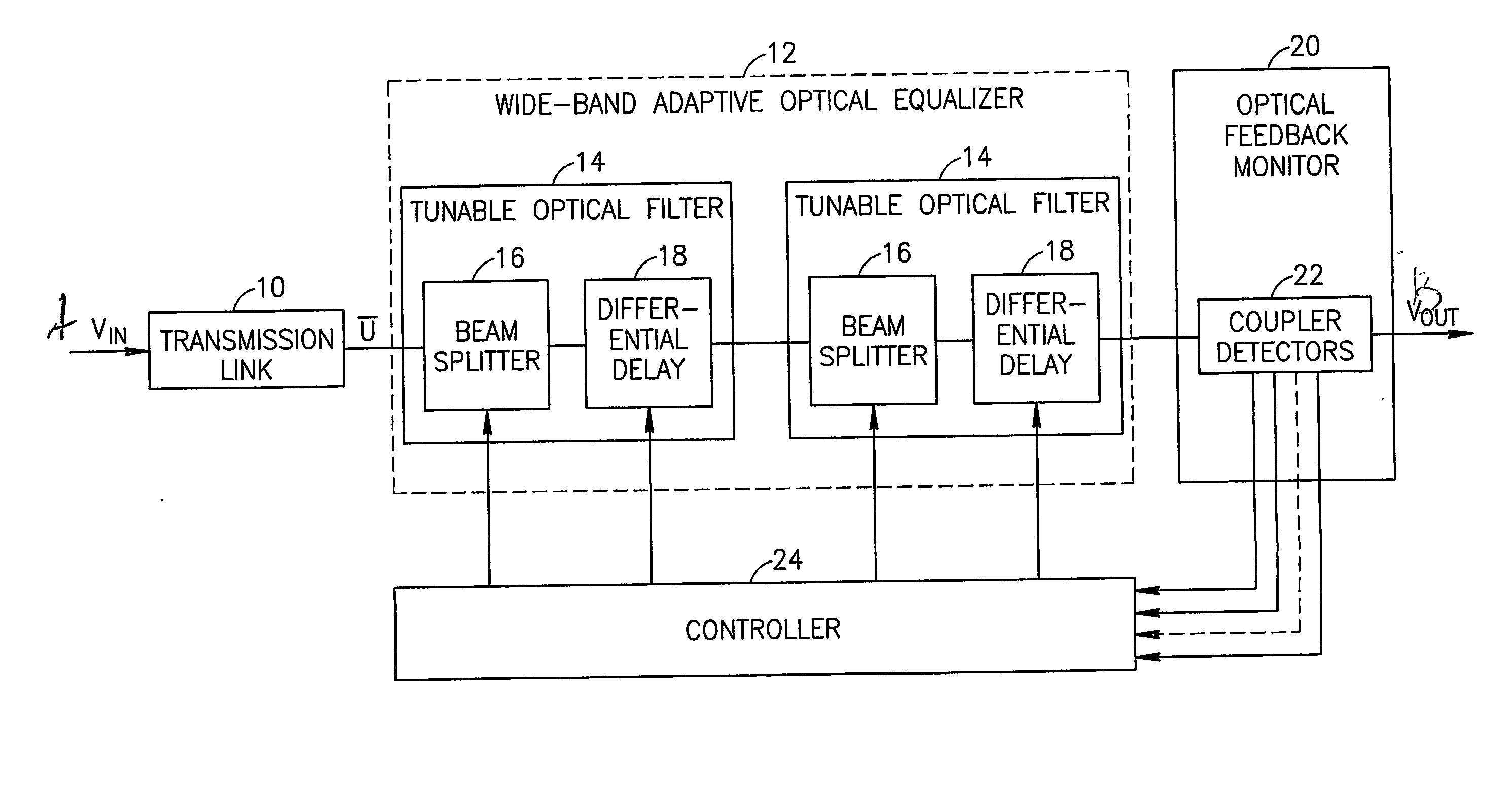
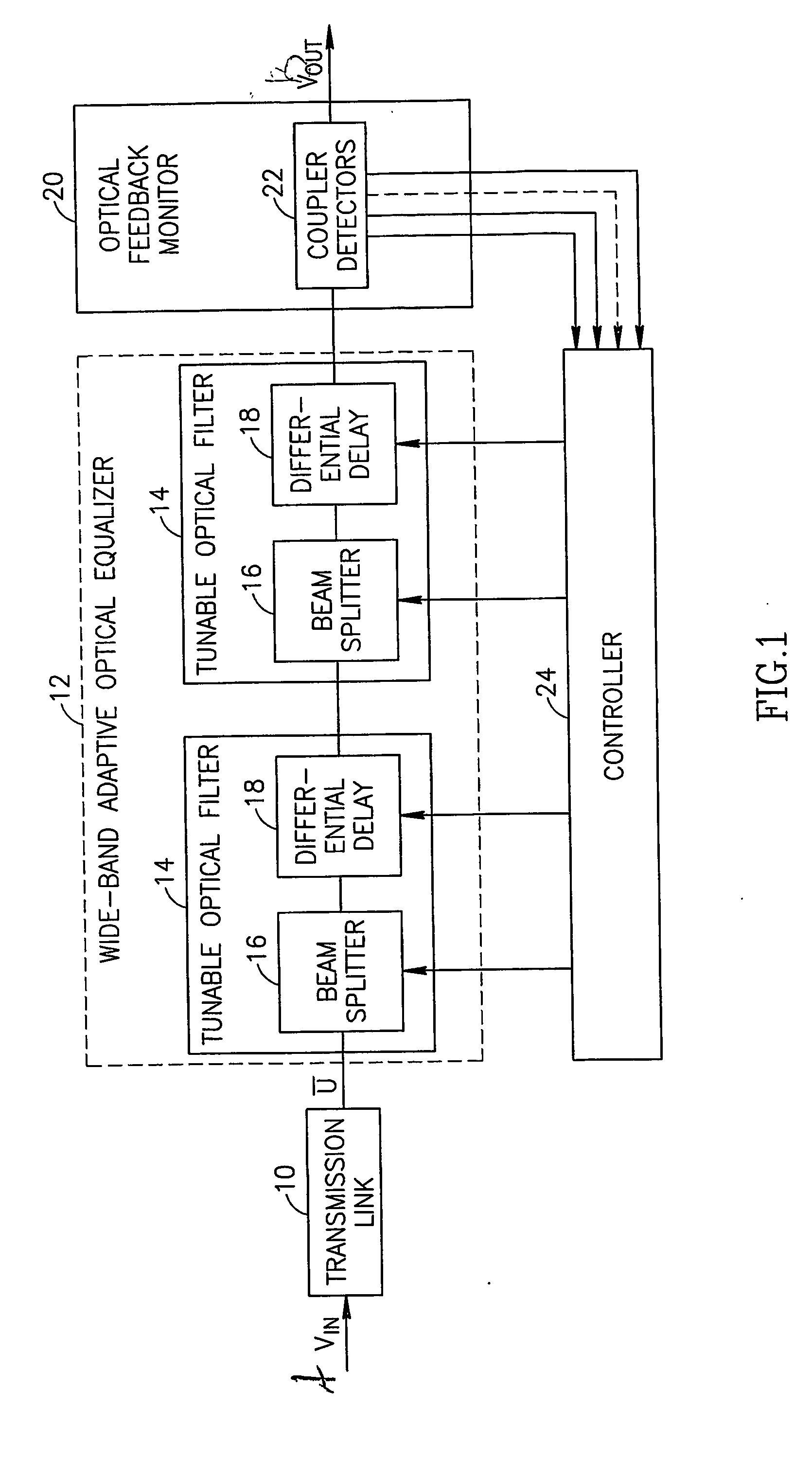
[0063]FIG. 1 schematically shows a multi-channel optical fiber transmission link 10 feeding a wideband adaptive optical equalizer (WAOE) 12. In the exemplary embodiment shown, WAOE 12 comprises a plurality of tunable optical filter units (TOFUs) 14, each of which comprises a beam splitter 16 and a differential delay element 18. Optionally, the beam splitter splits the beam based on the polarization of the beam. Alternatively, the splitting is not based on polarization. One or more TOFUs may also include a phase shifter (not shown). Differential delay element 18 is designed so that the delay caused by element 18 is different for different polarizations. Since a difference in time delay between the differently polarized waves is equivalent to a differential phase shift between the polarizations, these two concepts may be used interchangeably in the following discussion. The phase shifter and differential delay elements have substantially the same function, except that more controllabl...


PUM


Abstract

Apparatus for correcting distortion on an optical transmission link carrying a multiplicity of optical transmission channels, the apparatus comprising: an adjustable optical equalizer, through which a plurality of said channels pass; a field sampler that samples signals passing through said equalizer, such that a plurality of channels passing through the adjustable equalizer are separately sampled; and a controller that receives the samples, determines control parameters for the equalizer therefrom and adjusts the equalizer, responsive to said determined control parameters.

Description

RELATED APPLICATIONS [0001] The present application claims the benefit under 119(e) of U.S. provisional application No. 60 / 363,947 filed Mar. 14, 2002 disclosure of which is incorporated herein by reference.FIELD OF THE INVENTION [0002] The present invention relates to methods and apparatus for moderating distortion in optical pulses transmitted over an optical link of a communication network that are caused by dispersion of energy in the pulses during transmission over the link. BACKGROUND OF THE INVENTION [0003] An optical communication network transmits digital data between a transmitter and a receiver in the network in the form of pulses of light, usually representing zeros and ones, that are transmitted between the transmitter and receiver via an optical link comprising optical fibers. At a given transmission rate, pulses in a pulse train transmitted by the transmitter are transmitted during temporally contiguous, sequential periods of time, referred to as repetition periods, h...

Claims


Application Information

Patent Timeline
Patent Type & Authority Applications(United States)
IPC IPC(8): H04B10/2507H01S3/00H04B10/07H04B10/2525H04B10/2569H04J14/02
CPCH04B10/25073H04B10/25133H04B10/2543H04J14/0221H04B10/2572H04J14/02H04B10/255
Inventor HERSKOWITS, VARDAWEISS, ANTONY J.TIPRIS, MENACHEMLEVY, SHMUEL
Owner HERSKOWITS VARDA
Why Eureka
Try Eureka