Integral spark detector in fitting which supports igniter in gas turbine engine

Inactive Publication Date: 2005-08-11
GENERAL ELECTRIC CO
View PDF24 Cites 32 Cited by
  • Summary
  • Abstract
  • Description
  • Claims
  • Application Information

AI Technical Summary

Benefits of technology

[0020] The exposed auxiliary ground electrode can be detected by the fact that, when a spark occurs, a small current travels through the auxiliary ground electrode. When that curre

Problems solved by technology

Normal operation of an igniter in a gas turbine engi

Method used


Image

  • Integral spark detector in fitting which supports igniter in gas turbine engine
  • Integral spark detector in fitting which supports igniter in gas turbine engine
  • Integral spark detector in fitting which supports igniter in gas turbine engine

Examples


Embodiment Construction

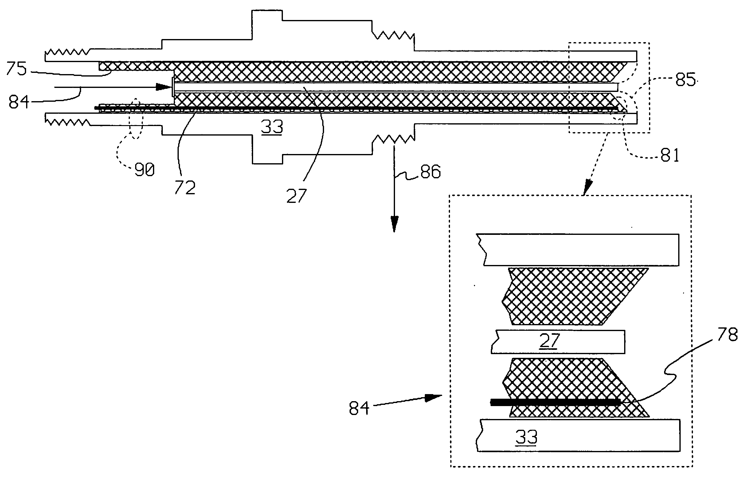
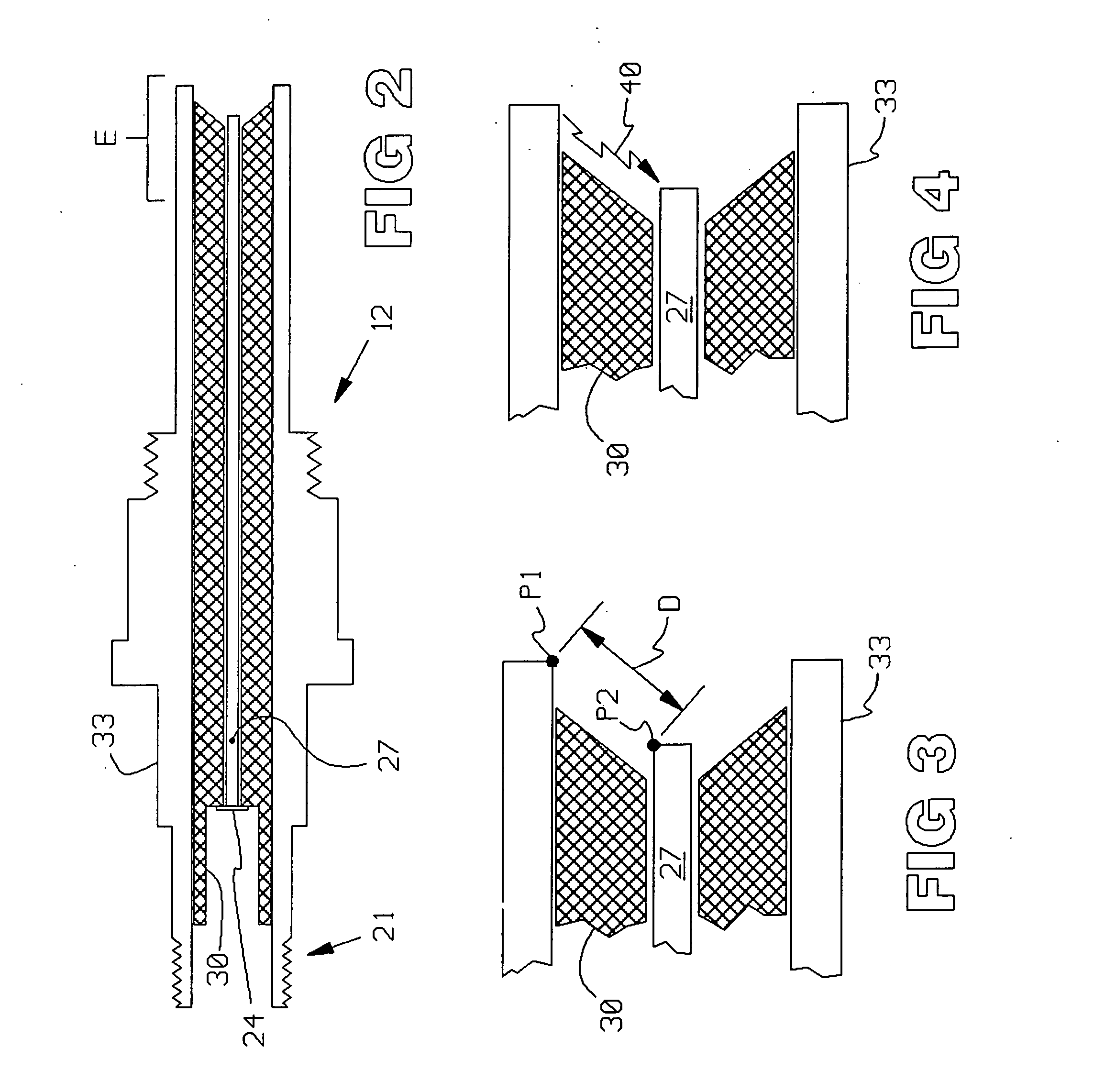
[0048]FIG. 2 illustrates an igniter 12 used in the prior art. An electrical connector (not shown) is threaded onto threads 21, and contains an electrical contact (not shown) which mates with the end 24 of electrode 27. Insulator 30 isolates electrode 27 from the shell 33 of the igniter 12.

[0049] End E of the igniter 12 is shown in FIGS. 3 and 4. A very simplified explanation of the physics involved in plasma generation will be given.

[0050] In operation, a high voltage is applied to the electrode 27, thereby creating a voltage difference, or potential difference, V between points P1 and P2 in FIG. 3. The electric field in that region equals the potential difference V divided by the distance D between the points P1 and P2. For example, if the voltage is 20,000 volts and the distance D is 10 millimeters, or 0.01 meter, then the electric field equals 20,000 / 0.01, or 2 million volts per meter.

[0051] The electric field is designed to exceed the dielectric breakdown strength of the mate...


PUM


Abstract

A system for detecting spark in an igniter for a gas turbine engine. An igniter generates a plasma, or spark, somewhat similar to an automotive spark plug. In the invention, an inductive pick-up is positioned adjacent the igniter, to detect current pulses in the igniter, to thereby infer the presence of spark. The pick-up can take the form of a coil embedded in a mounting bracket which is used to fasten the igniter to the engine.

Description

CROSS REFERENCE TO RELATED APPLICATIONS [0001] This Application is related to subject matter in the following patent applications, which are of common inventorship and filed concurrently herewith: [0002] SENSOR FOR DETECTION OF SPARK IN IGNITER IN GAS TURBINE ENGINE, Ser. No. ______; [0003] METHOD OF INFORMING PILOT OF AIRCRAFT OF SPARK DETECTED IN GAS TURBINE ENGINE, Ser. No. ______; [0004] PASSIVE, HIGH-TEMPERATURE AMPLIFIER FOR AMPLIFYING SPARK SIGNALS DETECTED IN IGNITER IN GAS TURBINE ENGINE, Ser. No. ______; [0005] DETECTING SPARK IN IGNITER OF GAS TURBINE ENGINE BY DETECTING SIGNALS IN GROUNDED RF SHIELDING, Ser. No. ______; and [0006] SPARK IGNITER FOR GAS TURBINE ENGINE, Ser. No. ______.FIELD OF THE INVENTION [0007] The invention relates to gas turbine engines, and igniters therein. BACKGROUND OF THE INVENTION [0008] This Background will explain why the lack of absolute certainty in lifetimes of igniters used in gas turbine aircraft engines can impose significant costs on t...

Claims


Application Information

Patent Timeline
IPC IPC(8): F02C7/266F02C9/00F02P17/12F23Q3/00F23Q23/10
CPCF02P2017/003F02C7/266
Inventor PONZIANI, ROBERT L.EARWOOD, ROY
Owner GENERAL ELECTRIC CO
Why Eureka
Try Eureka