Compact low NOx gas burner apparatus and methods

a gas burner, compact technology, applied in lighting and heating apparatus, combustion types, combustion using lump and pulverizing fuel, etc., can solve the problems of low turn down ratio and long flame length, and achieve the effect of short flame length and high turn down ratio

Active Publication Date: 2005-08-11
JOHN ZINK CO LLC
View PDF14 Cites 30 Cited by
  • Summary
  • Abstract
  • Description
  • Claims
  • Application Information

AI Technical Summary

Benefits of technology

[0008] By the present invention compact low NOx gas burner apparatus and methods are provided which meet the needs described above and overcome the deficiencies of the prior art. That is, the present invention provides improved gas burner apparatus and methods for discharging mixtures of fuel gas and air into furnace spaces wherein the mixtures are burned and flue gases having low NOx content are formed therefrom. In addition, the compact burner apparatus of this invention are smaller than most prior art burner apparatus, have high turn down ratios and produce short flame lengths.

Problems solved by technology

Further, the burner apparatus utilized heretofore to carry out the above described methods have generally been large, produce flames of long length and have low turn down ratios.

Method used


Image

  • Compact low NOx gas burner apparatus and methods
  • Compact low NOx gas burner apparatus and methods
  • Compact low NOx gas burner apparatus and methods

Examples


example 1

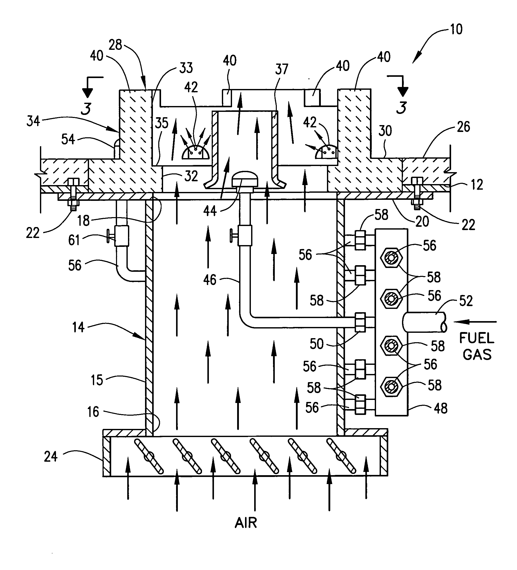
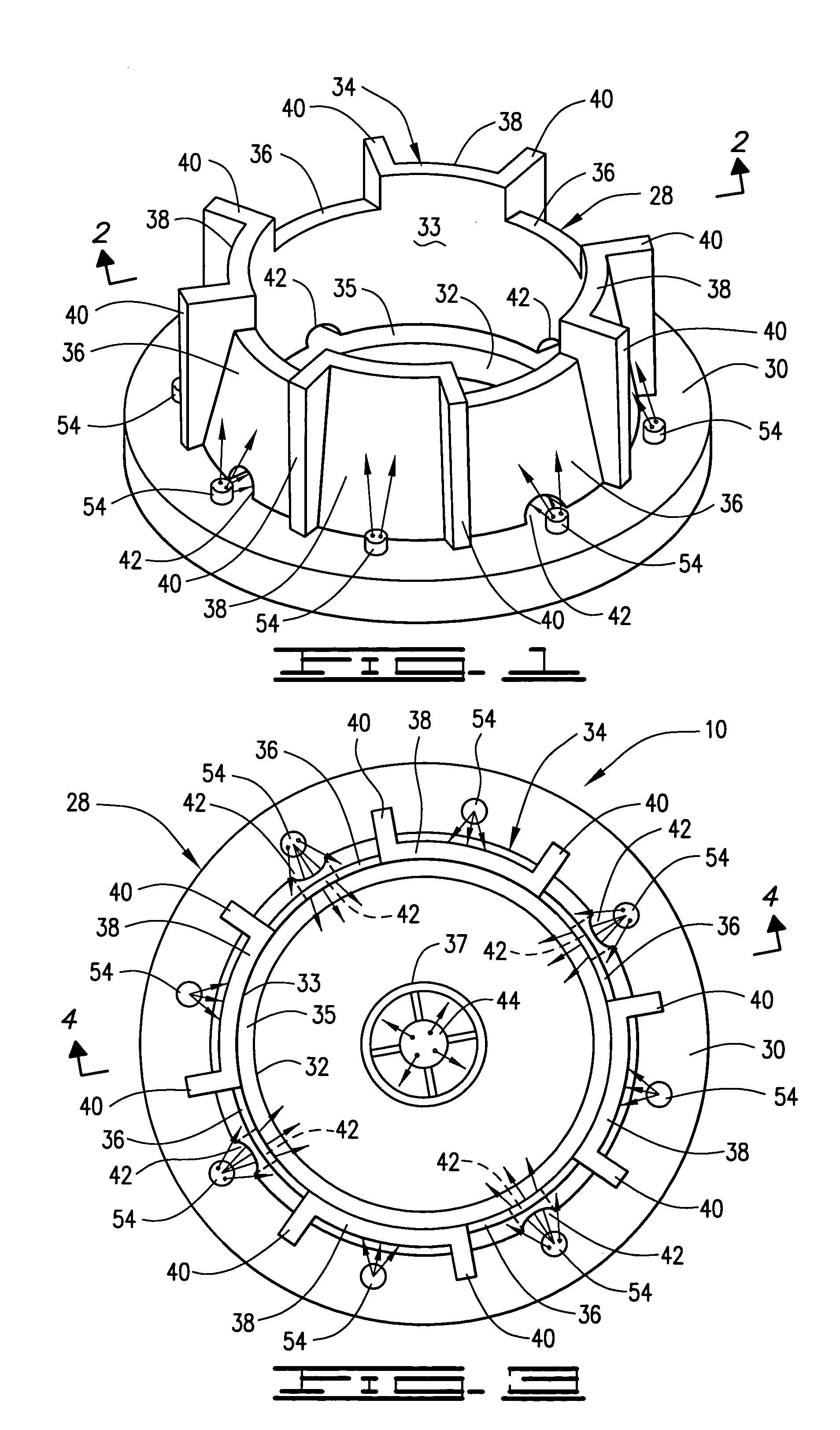
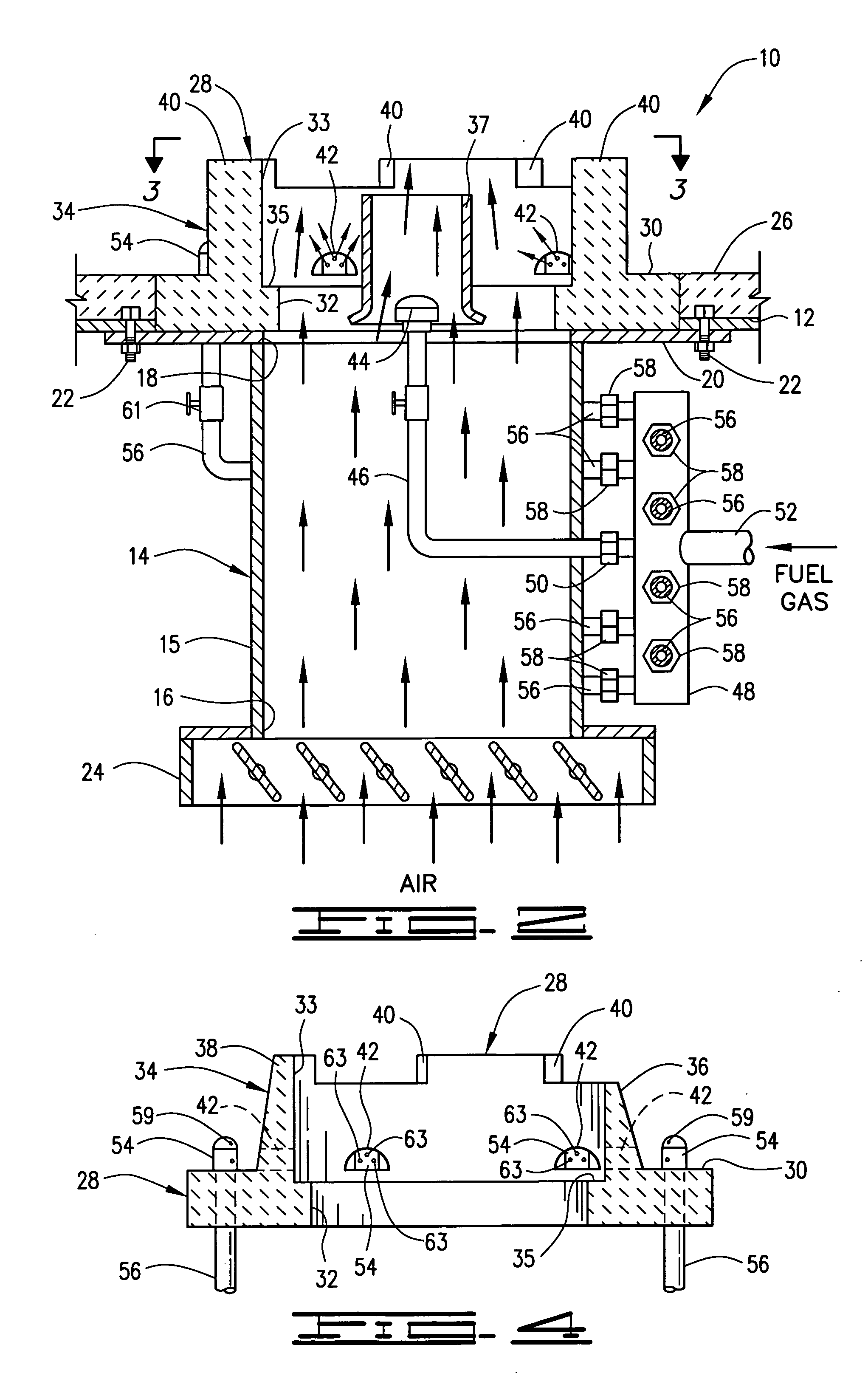
[0058] A burner apparatus 10 designed for a heat release of 8,000,000 BTU per hour by burning natural gas having a caloric value of 913 BTU / SCF was fired into a furnace space. Pressurized fuel gas was supplied to the manifold 48 of the burner 10 at a pressure of about 33 psig and a flow rate of about 8765 SCF / hour. A 20% by volume portion of the fuel gas (1753 SCF / hour) was used as primary fuel gas and was discharged within the opening 32 and wall 34 of the burner tile 28 by the fuel gas discharge nozzle 44 and by the fuel gas discharge nozzles 54 positioned adjacent to the openings 42 in the wall 40 of the burner tile 28. The remaining portion of the fuel gas, i.e., the secondary portion (at a rate of 7012 SCF / hour) was discharged into the furnace space by the nozzles 54 in separate fuel gas streams mixed with flue gases.

[0059] The rate of air introduced into the furnace space by way of the air register 24, the housing 14 and the burner tile 28 was at least 15% in excess of the st...

example 2

[0060] In order to see the flame pattern produced by the burner apparatus 10 when operated as described in Example 1 above, a computer simulation program was utilized. The software used was obtained from Fluent Inc. of Lebanon, N.H. The design of the burner was reconstructed in the simulation program in full three dimensional detail including all important features such as tile facets, fuel gas port drillings, flame holder tile ledge and complete air plenum configuration.

[0061] A three dimensional model of the furnace in which the burner apparatus was tested was then prepared and the burner model was mounted in the furnace model exactly like the test burner and furnace utilized in Example 1 except that the air entered the housing from the side instead of the bottom. The flow spaces in the burner model were divided into small volumes using the finite volume method and boundary conditions were applied, e.g., fuel pressure, flow rates, etc. at the entrances of the burner model. The so...


PUM


Abstract

Compact low NOx gas burner apparatus and methods for discharging fuel gas and air mixtures into furnace spaces wherein the mixture is burned in folded flame patterns and flue gases having low NOx content are formed are provided. A burner apparatus of the invention is basically comprised of a housing having a burner tile attached thereto and means for introducing air therein. The burner tile has an opening therein with a wall surrounding the opening which extends into a furnace space. The exterior sides of the wall are divided into sections by radially positioned baffles with alternate sections having the same or different heights and slanting towards the opening at the same or different angles. Primary fuel gas mixed with flue gases and air is discharged through the burner tile. Secondary fuel gas is discharged adjacent to the external slanted wall sections whereby the secondary fuel gas mixes with flue gases in the furnace space. The resulting fuel gas-flue gases streams mix with the fuel gas-flue gases-air mixture discharged through the burner tile and the resulting mixture is burned in the furnace space.

Description

[0001] This application is a Continuation-In-Part of application Ser. No. 10 / 775,978 filed on Feb. 10, 2004.BACKGROUND OF THE INVENTION [0002] 1. Field of the Invention [0003] The present invention relates to gas burner apparatus and methods for burning fuel gas-air mixtures whereby flue gases having low NOx content are produced. [0004] 2. Description of the Prior Art [0005] Emission standards are continuously being imposed by governmental authorities which limit the quantities of gaseous pollutants such as oxides of nitrogen (NOx) which can be emitted into the atmosphere. Such standards have led to the development of various improved gas burner designs which lower the production of NOx and other polluting gases. For example, methods and apparatus have been developed wherein all of the air and some of the fuel is burned in a first zone and the remaining fuel is burned in a second zone. In this staged fuel approach, an excess of air in the first zone acts as a diluent which lowers th...

Claims


Application Information

Patent Timeline
Patent Type & Authority Applications(United States)
IPC IPC(8): F23C6/04F23C7/00F23D14/02F23D14/58F23D14/70F23L1/00F23M3/00F23M5/02
CPCF23C6/047F23C7/008F23M5/025F23D14/58F23D14/70F23D14/02
Inventor CHUNG, I-PINGCHAMBERS, JESSE STEVENSCHNEPPER, CAROL ANNPOE, ROGER L.JAYAKARAN, JAIWANT D.WAIBEL, RICHARD T.CLAXTON, MICHAEL G.ZIMOLA, MARIANNEFOOTE, DARIN ROBERT
Owner JOHN ZINK CO LLC
Why Eureka
Try Eureka