Eureka AIR delivers breakthrough ideas for toughest innovation challenges, trusted by R&D personnel around the world.

Drive device for motor vehicle

Inactive Publication Date: 2005-08-11
EXEDY CORP
View PDF4 Cites 9 Cited by
  • Summary
  • Abstract
  • Description
  • Claims
  • Application Information

AI Technical Summary

Benefits of technology

[0010] Since this drive device employs an SR motor as its motor, it can produce a high torque in a low speed range, and can have a reduced size. Since the SR motor generates heat from its stator side, the drive shaft and bearings do not generate heat, and thus the motor can be easily cooled.
[0011] In another aspect of the present invention, the drive shaft is coaxial to the differential output shaft. In this drive device, since the drive shaft is coaxial to the differential output shaft, the motor does not protrude sideways with respect to the differential output shaft, and thus the device can be reduced in size.
[0015] The drive device according to the present invention can be small in size, and can easily cool the motor.

Problems solved by technology

In recent years, however, environmental issues have been highlighted so that attention has been focused on electric cars, which can reduce atmospheric pollution due to emissions as well as noise.
If the motor and reduction device are arranged in positions radially shifted from the differential output shaft, the electric motor and reduction device will occupy a large space, and thus increase the size and weight of the drive device itself.
Therefore, these drive devices bear large loads.
A DC motor cannot produce a large torque at a high speed, and an AC motor has a large body relative to its torque.
Therefore, large electric motors and thus large drive devices are often employed for obtaining required torque.
The heat of the rotor may be undesirably transmitted to the drive device and electric motor body and thus may damage the coil.

Method used


Image

  • Drive device for motor vehicle
  • Drive device for motor vehicle
  • Drive device for motor vehicle

Examples


Embodiment Construction

[0020] Embodiments of the invention will now be described with reference to the drawings.

[0021] (1) Structure of the Drive Device of a Motor Vehicle

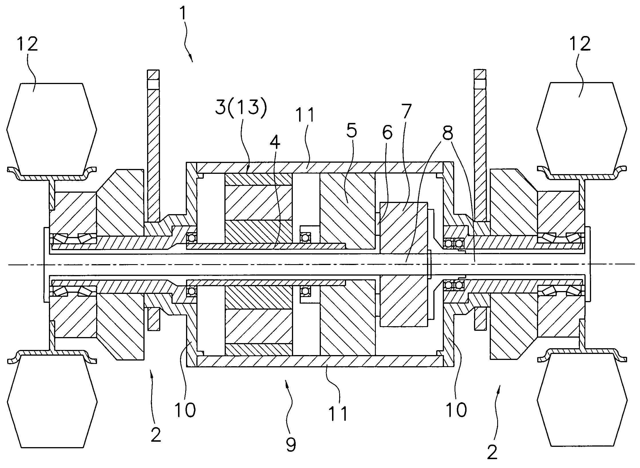
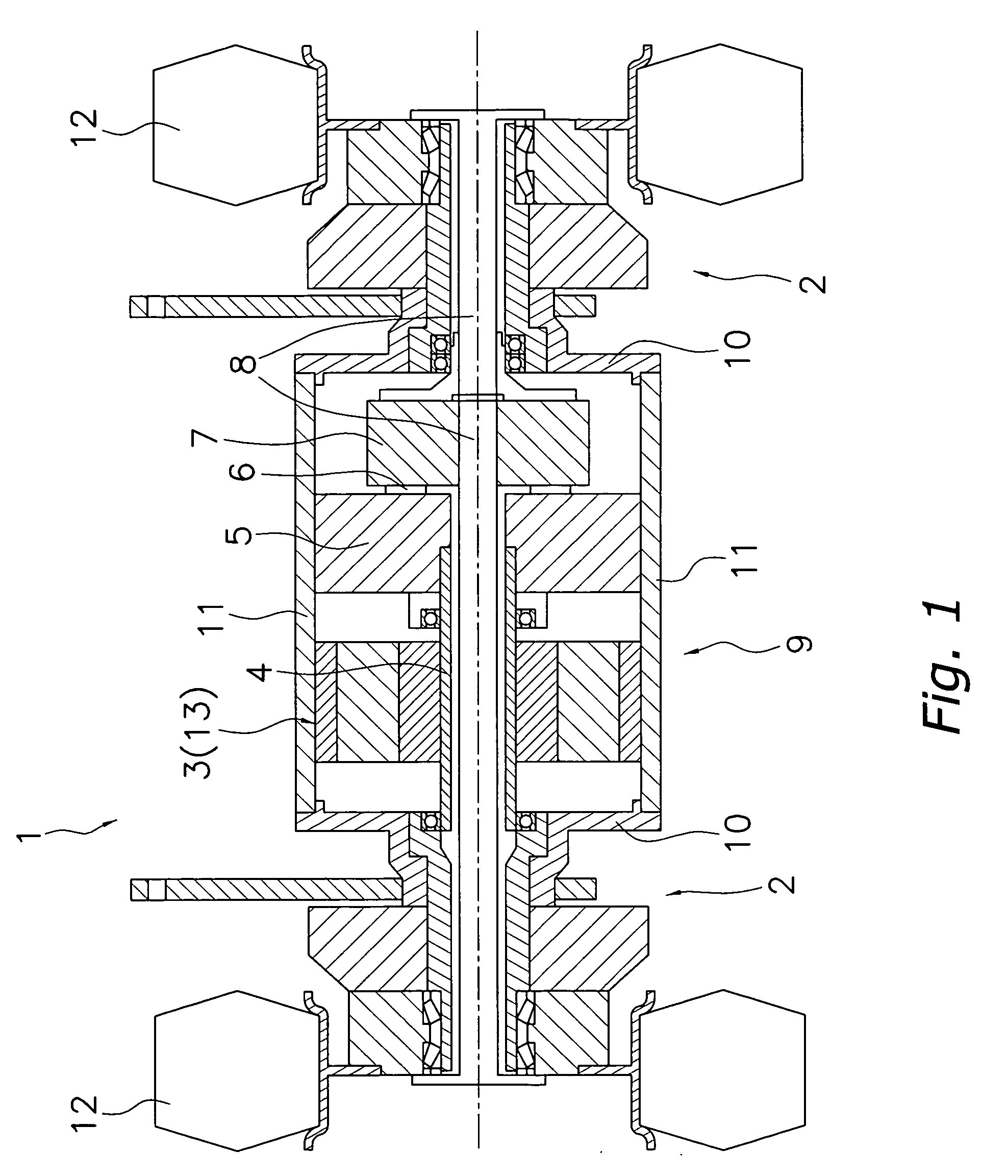
[0022] The structure of a drive device of a motor vehicle will now be described. FIG. 1 shows the structure of the drive device of the motor vehicle. A drive device 1 of the motor vehicle is primarily formed of an electric motor 3, a reduction device 5, a differential device 7, shaft support mechanisms 2, wheels 12 and a housing 9. The electric motor 3 is the power source of the vehicle, and drives a drive shaft 4 by means of electric power. The drive shaft 4 extends left and right from the motor 3. The drive shaft 4 is formed of a hollow cylindrical member, and has one end coupled to the reduction device 5.

[0023] The reduction device 5 is provided in order to reduce the rotation speed of the drive shaft 4, and includes a planetary gear drive. A reduction output shaft 6 of the reduction device 5 is coupled to the differential device 7...


PUM


Abstract

A drive device of a motor vehicle includes a reduction device coupled to a drive shaft of an SR motor, a differential device coupled to a reduction output shaft of the reduction device, a pair of differential output shafts respectively extending left and right from the differential device, and a pair of wheels respectively coupled to the differential output shafts.

Description

BACKGROUND OF THE INVENTION [0001] 1. Field of the Invention [0002] The present invention relates to a drive device of a vehicle driven by an electric motor. [0003] 2. Background Information [0004] In general, internal combustion engines are employed as drive devices of vehicles. In recent years, however, environmental issues have been highlighted so that attention has been focused on electric cars, which can reduce atmospheric pollution due to emissions as well as noise. Since an electric car uses an electric motor that employs electric power for driving as its power source, it does not discharge emissions, and produces less noise than the internal combustion engine. Therefore, not only in the automotive field, but also in the field of forklift trucks and other fields which conventionally employ both internal combustion engines and electric motors as drive devices, the rate at which electric motors are adopted has been increasing year after year for the purpose of improving the env...

Claims


Application Information

Patent Timeline
IPC IPC(8): B60K7/00B60K1/00B60K17/04B60K17/16B60L15/00F16H1/28F16H48/10F16H48/26H02K19/10
CPCB60K1/00B60K17/04H02K7/116B60Y2200/15H02K7/006B60K17/16
Inventor FUJITA, YASUHIKOMORI, HIROKISAKA, TAKAYUKI
Owner EXEDY CORP
Why Eureka
Eureka Blog
Learn More