Method and system for online condition monitoring of multistage rotary machinery

a multi-stage rotary machinery and condition monitoring technology, applied in the direction of rotary presses, printing, instruments, etc., can solve the problems of rotating errors, gear damage, vibration, gear damage,

Inactive Publication Date: 2005-08-11
WANG WILSON +2
View PDF3 Cites 26 Cited by
  • Summary
  • Abstract
  • Description
  • Claims
  • Application Information

AI Technical Summary

Benefits of technology

[0026] Advantageously, the present invention can diagnose doubling problems in multistage rotary machines such as printing machines in real-time in order to facilitate predictive maintenance and repairs. Another advantage of the invention is that it requires minimal hardware which can be readily installed.
is that it requires minimal hardware which can be readily installed.

Problems solved by technology

Doubling is a register error among different printing units, which occurs whenever the impression on a printing cylinder blanket does not accurately line-up with the previous image remaining on the web.
These rotation errors are induced by imperfections in the transmission systems within the units or the transmission links connecting different units.
These imperfections may result from vibration, gear damage, bearing fault, excessive run-out, misalignment, or component wear.
For presses with web support rollers between units, imperfections or damage in roller bearings increase the roller rotation friction and induce variation in the web tension between different rollers.
That web tension variation can cause doubling or smearing of the printed images, or even tear in the web.
If these deviations change over time and do not repeat, then they are considered to be the result of component wear or damage.
Meshing inaccuracy of the gear train driving plate and blanket cylinders is one of the main causes of the doubling problem in printing presses.
Thus, the doubling problem is typically caused by rotational non-synchronization among the corresponding rotary components (e.g. cylinders and rollers) in different printing press units, in other words, among the gears driving these rotary components.
One problem in detecting and preventing doubling is the difficulty in quantitatively determining rotational dissimilarities in real-time among the rotary components (e.g. gears) in different printing press units.
A disadvantage of Gross, for example, is that it is difficult to detect gear damage using FFT techniques as spectral analysis usually fails to pick up the gear tooth faults.
Since multistage rotary machines, such as printing presses, have complicated mechanical transmission systems, the spectra involved have too many spectral components to analyze effectively.
Another disadvantage with existing systems is that they are not effective at determining gear run-out (which is related to factors such as bearing wear) or in using run-out information to diagnose doubling problems.
Another disadvantage with existing systems such as that proposed by Hill, et al. is that if doubling is caused by factors such as vibration, it is difficult to offset the rotational non-synchronization among different units by the adjustment of the rotational speed of the driving motors in different units.
A further disadvantage of existing systems (e.g. those disclosed by Gagne, et al., Guaraldi, et al., and Burke, et al.) is that they focus their techniques mainly on the gears driving the plate and blank cylinders.
In fact, a fault with any rotary component of the printing press transmission system may cause a doubling problem.

Method used


Image

  • Method and system for online condition monitoring of multistage rotary machinery
  • Method and system for online condition monitoring of multistage rotary machinery
  • Method and system for online condition monitoring of multistage rotary machinery

Examples


Embodiment Construction

[0032] In the following description, numerous specific details are set forth to provide a thorough understanding of the invention. However, it is understood that the invention may be practiced without these specific details. In other instances, well-known software, circuits, structures and techniques have not been described or shown in detail in order not to obscure the invention. The term “diagnostic system” is used herein to refer to any machine for processing data, including the computer systems and network arrangements described herein.

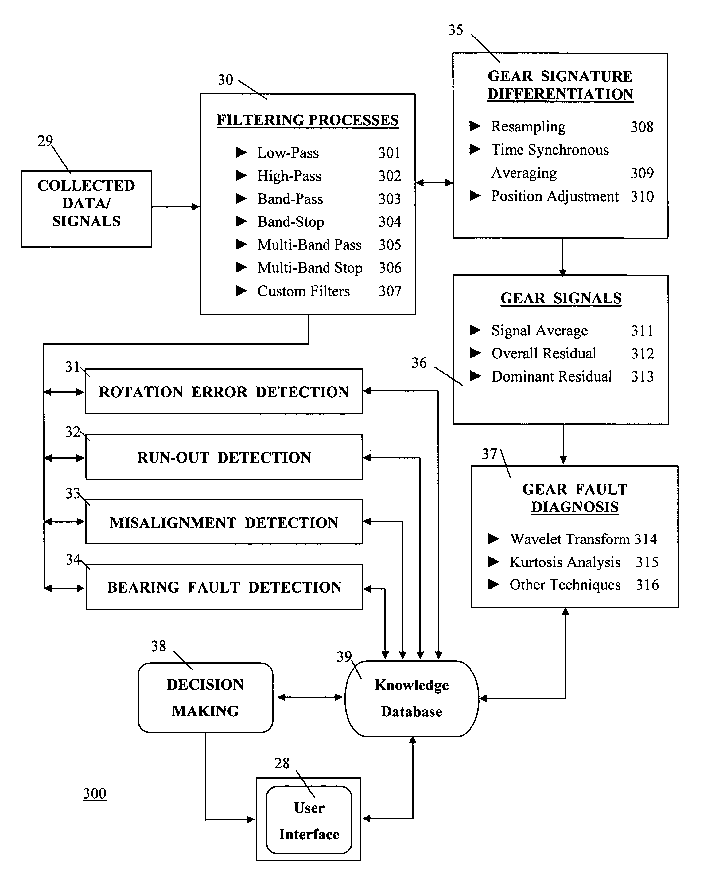
[0033] System. In general, the present invention provides a real-time diagnostic system for health condition monitoring of rotary machinery in order to facilitate predictive maintenance and repair. More particularly, the present invention provides a real-time diagnostic system for multistage rotary machinery such as printing presses to monitor rotation non-synchronization (i.e. doubling) at different stages, to isolate the sources of doubling pro...


PUM


Abstract

The present invention provides a method and system for online health condition monitoring of rotary machinery such as printing presses. The rotary machines have one or more stages and each stage has one or more rotary components. The method comprises the steps of: receiving one or more signals from sensors at each of the rotary units or bearing housings; generating an error matrix and diagnosing rotation synchronization errors among the different stages; generating error matrices using different signal processing techniques and diagnosing the health conditions of rotary components such as gears, bearings and shafts; and identifying the stages and rotary components having imperfections by comparing the current error matrices to stored reference error matrices. The present invention can also be used in other applications involving rotational components such as automobiles, airplanes, and power turbines to name a few.

Description

[0001] This application is a continuation of U.S. patent application Ser. No. 10 / 661,775, filed Sep. 15, 2003, and incorporated herein by reference, which claims priority from U.S. Provisional Patent Application No. 60 / 413,901 filed Sep. 27, 2002, and incorporated herein by reference.FIELD OF THE INVENTION [0002] This invention relates to the field of diagnostic systems for rotary machines, and more specifically, to a method and system for diagnosing non-synchronization related imperfections, such as doubling, in multistage rotary machines such as printing presses. BACKGROUND OF THE INVENTION [0003] Doubling is a major quality control concern in the operation of multistage rotary machinery such as printing presses. Doubling is a register error among different printing units, which occurs whenever the impression on a printing cylinder blanket does not accurately line-up with the previous image remaining on the web. As the name suggests, doubling appears in a printed image as two impr...

Claims


Application Information

Patent Timeline
Patent Type & Authority Applications(United States)
IPC IPC(8): B41F13/00B41F13/004B41F13/012B41F13/12B41F33/00B41F33/02G05B23/02G06F19/00
CPCB41F13/0045B41F13/012G05B23/0237B41F33/0009B41F13/12
Inventor WANG, WILSONGOLNARAGHI, FARIDISMAIL, FATHY
Owner WANG WILSON
Why Eureka
Try Eureka