Pressure sensor having a silicon chip on a steel diaphragm

a pressure sensor and silicon chip technology, applied in the direction of fluid pressure measurement, water supply installation, instruments, etc., can solve the problems of diaphragm corruption, negative affecting the junction or also the functional elements of the pressure sensor, and increasing the susceptibility of the pressure sensor to mechanical destruction

Active Publication Date: 2005-08-18
ROBERT BOSCH GMBH
View PDF3 Cites 20 Cited by
  • Summary
  • Abstract
  • Description
  • Claims
  • Application Information

AI Technical Summary

Benefits of technology

[0009] Advantageously, the first diaphragm of the first component and the first region of the second component are joined by a first joining material. This permanent bond allows movements of the first diaphragm to be transferred to the thin first region without appreciable loss.
[0010] Moreover, by using an adhesive and / or solder or seal glass solder as a first joining material, it is possible to do without a special surface structure of the first diaphragm because the first joining material can cover the diaphragm surface uniformly and homogeneously. Moreover, the first component may have a base in addition to the first diaphragm. In a further embodiment, this base can be used to produce a further bond between the base and the second region of the second component using a second joining material. The advantage of this second bond is that the contact area of the second component with the first component is enlarged. Thus, the transition from the thin first region to the thick second region of the second component is mechanically relieved. The second joining material proposed is ductile material which is relatively soft when not stressed and becomes harder under the action of pressure. Thus, after joining the first component to the second component, a bonding wire can be applied to the surface of the second component without causing the second component to break.
[0012] Advantageously, the first component may contain steel, ceramic, Invar, Kovar, or an iron-nickel alloy as the first material. One particular embodiment of the present invention proposes that only the first diaphragm be made of a metal or steel. Thus, it is possible to use steels that are particularly suitable for pressure sensor diaphragms. In this connection, it is possible to use high-grade steels that are particularly resistant to corrosion, for high-pressure applications, steels of particularly high tensile strength or alloys whose thermal expansion coefficients are matched to silicon. Moreover, the second component may be composed of a semiconductor material. In one particular embodiment of the present invention, the second component is composed of silicon or a silicon compound. It is also advantageous to produce a second diaphragm in the thin first region. In order to measure the pressure variable, the second component may contain at least one piezoelectric resistor which experiences a change in resistance as a function of the vertical movement of the first diaphragm. In this connection, provision is preferably made for the at least one piezoelectric resistor to be located in or on the first region, in particular on the second diaphragm, of the second component. The second component may have at least one circuit trace via which an electrical signal generated as a function of a pressure applied to the first diaphragm is transmitted to an evaluation circuit. Advantageously, a fourth region on the second component accommodates at least part of an electrical circuit, which may be separated from the second region by a third region and / or can be used to evaluate the change in resistance of the piezoresistors when measuring the pressure variable. By separating the electrical circuit or electrical components by relief grooves, it is possible to suppress thermally or stress-induced mechanical strains, which could possibly corrupt the measured value.
[0017] Moreover, a semiconductor chip configuration including a thin first region featuring the diaphragm and a thicker second region at the edge of the semiconductor substrate is advantageous during the alignment of the semiconductor chip to the steel substrate, the proviso being that proper dimensions are chosen.
[0018] In accordance with one further embodiment of the present invention, the first and second components are processed separately before they are joined by the first joining material. This has the advantage that sensitive process steps required for a component (such as etching the cavity, making the circuit traces and / or the circuit) can be carried out without being affected by process steps during the production of the other component.

Problems solved by technology

In this context, different thermal expansions may lead to thermal stresses, which negatively affect the junctions or also the functional elements of a pressure sensor, such as the diaphragm and / or the strain gauge.
This may result in corruption of the measured signal or increased susceptibility of the pressure sensor to mechanical destruction.

Method used


Image

  • Pressure sensor having a silicon chip on a steel diaphragm
  • Pressure sensor having a silicon chip on a steel diaphragm
  • Pressure sensor having a silicon chip on a steel diaphragm

Examples


Embodiment Construction

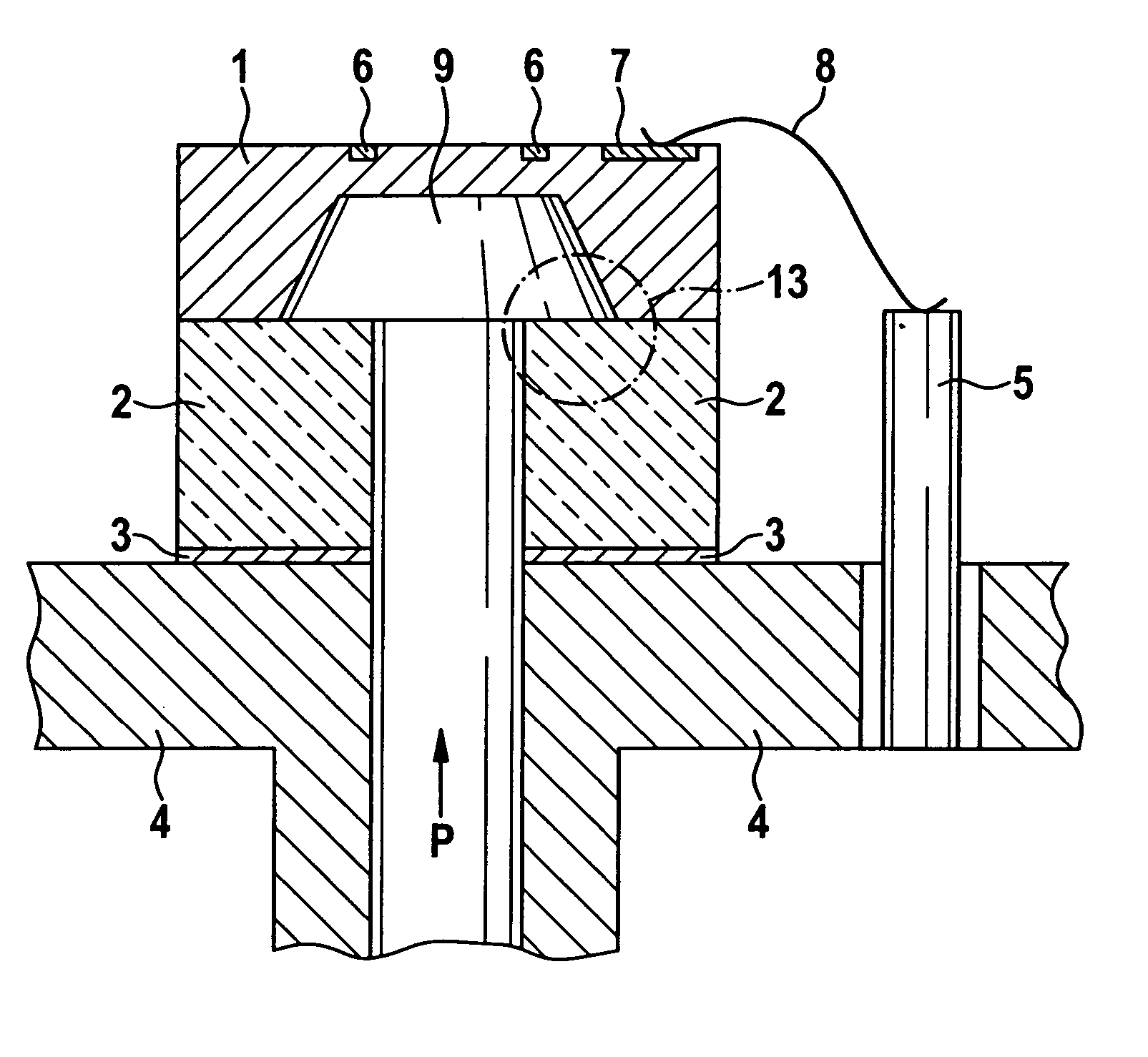
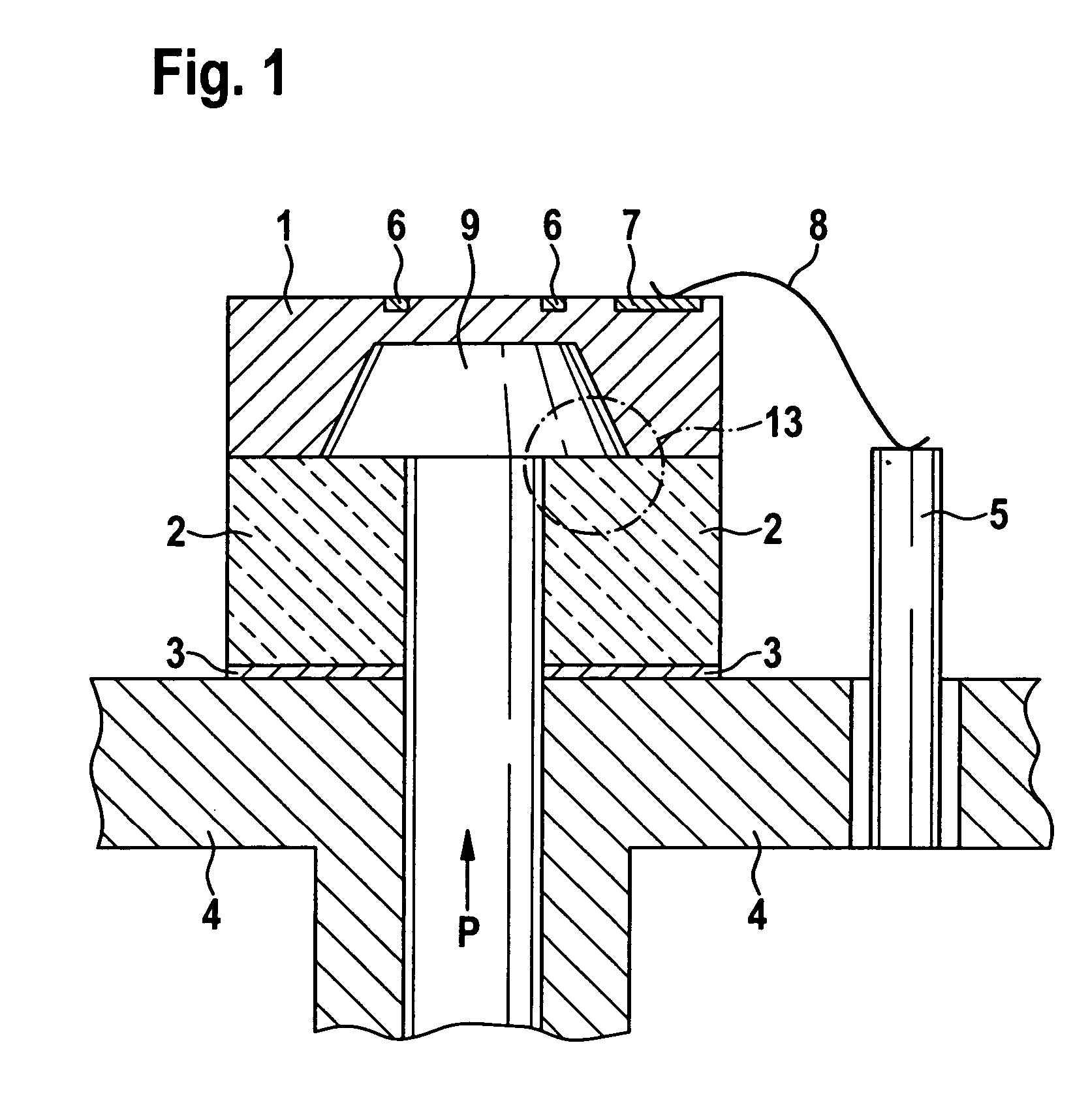
[0025] A sensor design as shown in FIG. 1 represents the state of the art. There, a sensor chip 1 is anodically bonded to an intermediate glass layer or a glass base 2 composed of sodium-containing glass. Glass base 2 is metallized on the backside and attached to a metal base 4 (for example, a T08 base) by solder 3. The conventional sensor chip 1 can be composed of a pure resistance bridge featuring piezoresistive resistors 6, or be combined with an evalluation circuit 7 connected via circuit traces, which are integrated on sensor chip 1 in a semiconductor process along with piezoresistors 6. Piezoresistive resistors 6 and / or evaluation circuit 7 are connected via at least one corresponding bonding wire 8 to a terminal 5 which allows the measured signals to be transmitted to control systems.

[0026] In the conventional pressure sensor shown in FIG. 1, the diaphragm is made by anisotropic etching, for example, using KOH or TMAH. However, in the case of the sensor design described, usi...


PUM

PropertyMeasurementUnit
pressure variableaaaaaaaaaa
temperature expansion coefficientaaaaaaaaaa
temperatureaaaaaaaaaa

Abstract

A micromechanical device for measuring a pressure variable and a method for manufacturing a micromechanical pressure sensor. The sensor includes, two components; a first component featuring a diaphragm made of a first material, and a second component of a second material. This second component is designed to have a thin first region and a thick second region. The first and second components are permanently joined together via the first diaphragm and at least a portion of the first region. The materials are selected such that the temperature expansion coefficient of the first material is higher than that of the second material. The first and second components are joined in such a manner that a lateral expansion of the first diaphragm caused by temperature changes is transferred to the first region of the second component as a lateral expansion as well.

Description

FIELD OF THE INVENTION [0001] The present invention relates to a micromechanical device for measuring a pressure variable and a method for manufacturing a micromechanical device. BACKGROUND INFORMATION [0002] Micromechanical pressure sensors are frequently composed of different components (such as substrate, base, housing), which are joined together and have different thermal expansion coefficients, as illustratively described in German Patent Application No. DE 103 30 252 A1. In this context, different thermal expansions may lead to thermal stresses, which negatively affect the junctions or also the functional elements of a pressure sensor, such as the diaphragm and / or the strain gauge. This may result in corruption of the measured signal or increased susceptibility of the pressure sensor to mechanical destruction. [0003] German Patent No. DE 41 30 044 C2 describes a semiconductor pressure sensor having a silicon substrate, a diaphragm formed from the substrate, strain gauges, as w...

Claims


Application Information

Patent Timeline
Patent Type & Authority Applications(United States)
IPC IPC(8): B81B3/00G01L9/00H01L29/84
CPCG01L9/0055G01L9/0048G01L19/146
Inventor BENZEL, HUBERTHABIBI, MASOUDMOERSCH, GILBERTGUENSCHEL, ROLANDGEBAUER, JAN
Owner ROBERT BOSCH GMBH
Why Eureka
Try Eureka