Perforated skin structure for laminar-flow systems

a perforated skin and flow system technology, applied in the direction of air flow influencers, fuselages, drag reduction, etc., can solve the problems of inefficient or dysfunctional laminar flow control, flow to undergo immediate and irrecoverable transition to turbulence, and limit the suction amount that can be applied to 3-d boundary layers, etc., to achieve high thermal conductivity and reduce energy

Inactive Publication Date: 2005-08-18
AIRBUS OPERATIONS GMBH
View PDF18 Cites 26 Cited by
  • Summary
  • Abstract
  • Description
  • Claims
  • Application Information

AI Technical Summary

Benefits of technology

[0028] to provide a perforated skin structure that has high thermal conductivity.
[0029] The invention further aims to avoid or overcome the disadvantages of the prior art, and to achieve additional advantages as apparent from the present description, claims, abstract, and drawings.
[0030] The above objects have been achieved according to the invention in a laminar flow control arrangement including a perforated skin constructed with numerous perforations arranged in a pattern having a spatial spectrum that is essentially absent of energy at predetermined wavelengths. The term “essentially absent of energy” must be understood in relation to the additional peak energy above the average background “noise” level of energy resulting from the unavoidable machining inaccuracies and the like. Preferably, these predetermined wavelengths are the wavelengths of predetermined flow instabilities, and especially the most unstable disturbances appearing in the boundary layer flowing over the perforated skin, particularly at the design operating conditions of the laminar-flow control arrangement, such as at the aircraft cruise flight conditions of the pertinent aircraft.
[0031] The preferred embodiment or mode of the inventive pattern and shape of perforations comprises a plurality of longitudinally extending perforated areas or groups of rows of perforations, which are spaced apart from each other, and which are called “bundles” herein. Most preferably, these longitudinally extending bundles are aligned essentially parallel, (e.g. within 10° of preferably 5° of parallel) to the leading edge of the surface provided with the perforations, for example the perforated skin of the airfoil. The term “essentially parallel” also allows for a slight convergence of the bundles relative to each other, from the root end to the tip end of the airfoil, for example following the taper of the airfoil. The bundles are separated laterally from one another by non-perforated areas.
[0032] Each bundle comprises a plurality of perforations arranged to yield a spatial spectrum of each respective bundle that has reduced energy or is preferably essentially absent of energy (above a general or average “noise” energy level) at predetermined wavelengths. This is especially

Problems solved by technology

Since the abatement and elimination of such flow instabilities is a primary purpose of the laminar-flow control system, as recognized and developed by the present inventor, all previously existing or suggested perforation patterns of conventional surface suction systems yield either inefficient or dysfunctional laminar-flow control results.
It has also been observed that there is a clear limit to the amount of suction that can be applied to 3-D boundary layers, beyond which the flow in the vicinity of each hole becomes sufficiently distorted to cause the flow to undergo an immediate and irrecoverable transitio

Method used


Image

  • Perforated skin structure for laminar-flow systems
  • Perforated skin structure for laminar-flow systems
  • Perforated skin structure for laminar-flow systems

Examples


Embodiment Construction

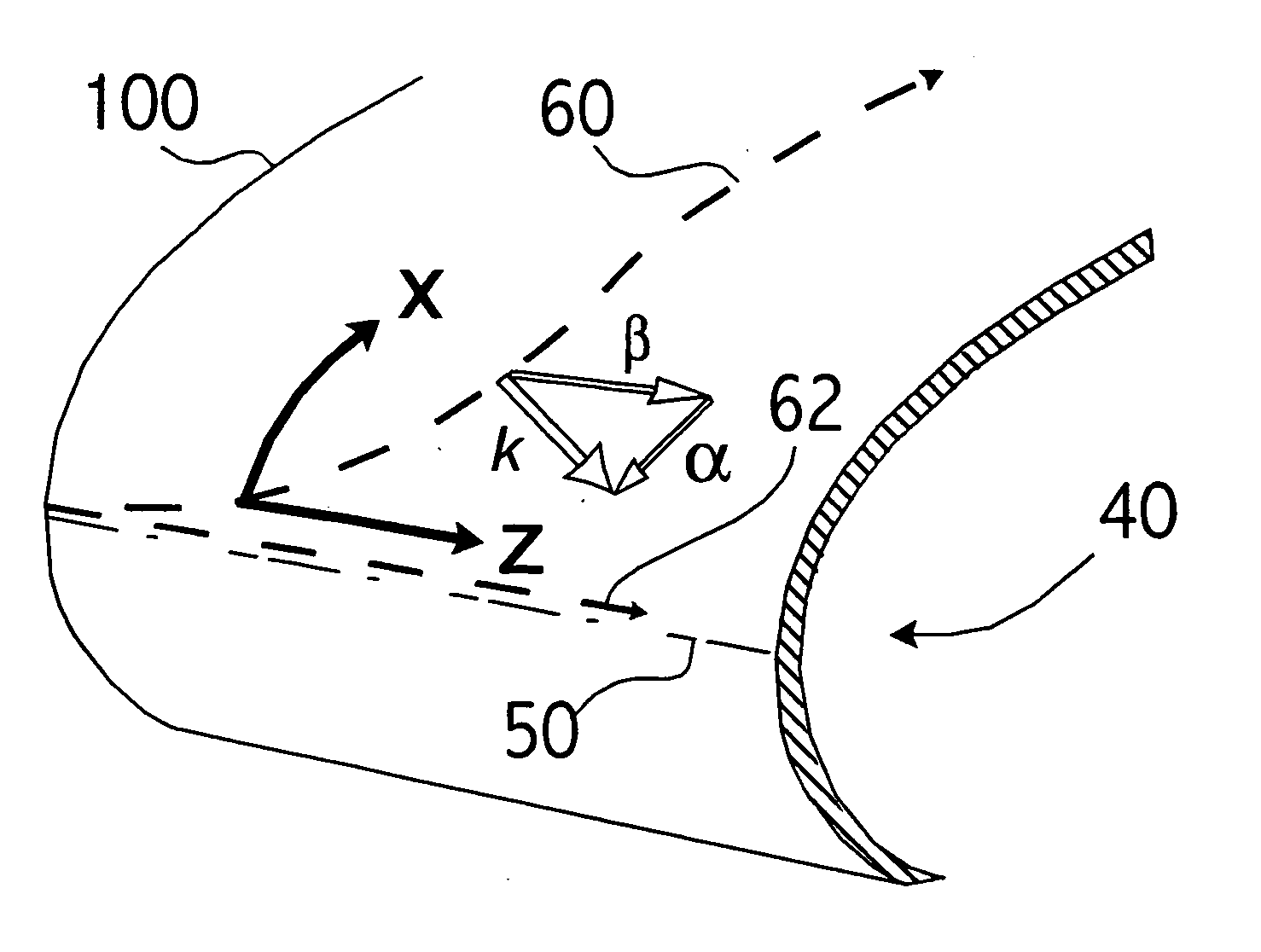
[0051] The invention will now be described in connection with an example relating to an airfoil, such as the vertical fin or the main lifting wing of an aircraft, which represent highly effective and preferred applications of the invention. As a reference for the following discussion, FIG. 1 schematically shows the basic geometry of a representative aerodynamic body 40 such as an airfoil portion of a lifting wing or the like of an aircraft. The aerodynamic body 40 has an outer skin 100 and a leading edge 50. When this aerodynamic body 40, or especially the airfoil 40, is moving through the air, the free-stream airflow impinges onto and grazes along the aerodynamic body 40, thereby creating a boundary layer airflow over the outer skin 100. The aerodynamic body 40 and particularly its leading edge 50 is positioned with a rearward sweep angle relative to the free-stream airflow direction, and consequently, the airflow attaches along the leading edge 50 to form a streamline 62 of rectil...


PUM


Abstract

The outer skin (100) of an aerodynamic body (40) has perforations (200) arranged in particular patterns in respective spanwise extending groups or bundles (250). Each perforation is preferably a micro-slot with a length of 100 to 3000 μm and a width of 50 to 250 μm. Air is sucked through the micro-slots from the boundary layer flowing over the outer skin, to achieve boundary layer control. In each bundle, the pattern, size, orientation, and other parameters of the micro-slots are designed to achieve mutual destructive interference of flow disturbances arising due to the suction, to minimize the excitation of flow instabilities in the boundary layer. Particularly, the spatial spectrum of the perforation pattern of a given bundle is essentially absent of significant energy at predetermined wavelengths of predetermined flow instabilities that otherwise appear in the boundary layer air flow. The aerodynamic body further includes supporting ribs (300) extending parallel to the perforation bundles (250) and a perforated inner plate (400) providing a throttling control of the suction flow through groups of the bundles.

Description

CROSS-REFERENCE TO RELATED APPLICATION [0001] This application is based on and claims the priority, under 35 U.S.C. §119(e) and PCT Article 8, of U.S. Provisional Application 60 / 373,653, filed on Apr. 18, 2002, the entire disclosure of which is incorporated herein by reference.TECHNICAL FIELD [0002] This invention relates to the construction of a perforated skin structure for the application of laminar-flow control via suction of boundary layer air. BACKGROUND ART [0003] It is generally known in the art that the laminar-flow conditions of the boundary layer of a fluid flowing over the surface of a body can be influenced by various devices. It is further known that stabilizing the laminar-flow conditions of the boundary layer can reduce the resulting skin friction between the fluid and the body. This is especially pertinent, for example, in the field of aircraft construction, whereby the improvement of the laminar-flow of the boundary layer and the resulting lower skin friction can a...

Claims


Application Information

Patent Timeline
IPC IPC(8): B64C1/00B64C21/06
CPCB64C21/06Y02T50/166B64C2230/22B64C2230/04B64C2230/06Y02T50/10
Inventor BERTOLOTTI, FABIO P.
Owner AIRBUS OPERATIONS GMBH
Why Eureka
Try Eureka