Drive unit and driving method of liquid crystal panel, and liquid crystal projector using the same

a technology of driving unit and liquid crystal panel, which is applied in the direction of color television details, picture reproducers using projection devices, instruments, etc., can solve the problems of generating a difference in response speed, and achieve the effect of improving picture quality at the time of displaying moving pictures and the like, uniform response speed of each liquid crystal panel, and low cos

Inactive Publication Date: 2005-08-18
NEC CORP
View PDF7 Cites 31 Cited by
  • Summary
  • Abstract
  • Description
  • Claims
  • Application Information

AI Technical Summary

Benefits of technology

[0027] An object of the present invention is to improve the picture quality at the time of displaying a moving picture by making the response speeds of each liquid crystal panel uniform even in the case where there is a difference generated in the temperatures of each liquid crystal panel caused by irradiation of light with different energies onto three liquid crystal panels for each color of R, G, B being used in a three-plate-type liquid crystal projector.

Problems solved by technology

Therefore, there is a difference generated in the temperatures of the liquid crystal panels, which causes generation of a difference in the response speeds.

Method used


Image

  • Drive unit and driving method of liquid crystal panel, and liquid crystal projector using the same
  • Drive unit and driving method of liquid crystal panel, and liquid crystal projector using the same
  • Drive unit and driving method of liquid crystal panel, and liquid crystal projector using the same

Examples


first embodiment

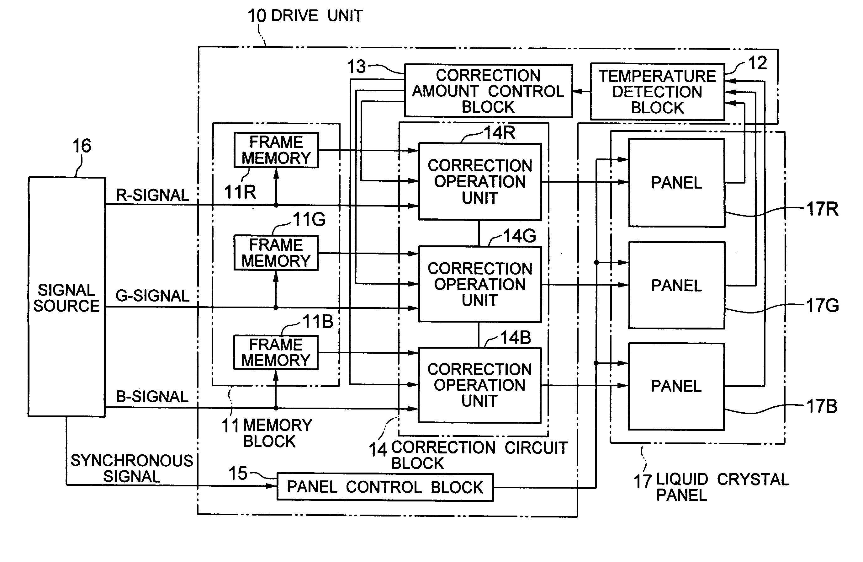
[0070]FIG. 4 is a block diagram showing the drive unit according to the present invention. Description will be provided hereinafter by referring to the drawing.

[0071] A drive unit 10 of the embodiment is an electronic circuit used in a three-plate-type liquid crystal projector, which comprises a memory block 11, a temperature detection block 12, a correction amount control block 13, a correction circuit block 14, a panel control block 15, and the like.

[0072] The memory block 11 includes frame memories 11R, 11G, 11B for R, G, B for holding video signals in each color of R, G, B supplied from a signal source 16 at least for one frame period. A liquid crystal panel 17 includes panels 17R, 17G, 17B for the three primary colors of R, G, B. The temperature detection block 12 detects the temperatures of each of the panels 17R, 17G, 17B or the temperatures of the peripheries, respectively.

[0073] The correction amount control block 13 controls the correction amount applied to the video sig...

second embodiment

[0089]FIG. 6 is a block diagram for showing the drive unit according to the present invention. Description will be provided hereinafter by referring to the drawing. However, the same reference numerals are applied to the same components as the ones shown in FIG. 4 and the description will be omitted.

[0090] A drive unit 20 of the embodiment is an electronic circuit, comprising a memory block 21, a temperature detection block 22, a correction amount control block 23, a correction circuit block 24, an operation block 25, a panel control block 15 and the like. This is used in a three-plate-type liquid crystal projector.

[0091] The memory block 21 holds only the video signal of R-color supplied from the signal source 16 at least for one frame period.

[0092] The temperature detection block 22 detects the temperature of only the liquid crystal panel 17R or that of the peripheries. The correction amount control block 23 controls the correction amount applied to the video signals. The correc...

third embodiment

[0102]FIG. 8 is a block diagram for showing the drive unit according to the present invention. Description will be provided hereinafter by referring to the drawing.

[0103] A drive unit 30 of the embodiment shown in FIG. 8 is an electronic circuit, comprising a radio-frequency conversion block 31, a memory block 11, a temperature detection block 12, a correction amount control block 13, a correction circuit block 14, a panel control block 15 and the like. This is used in a three-plate-type liquid crystal projector.

[0104] The radio-frequency conversion block 31 converts the video signals of each of the colors of R, G, B supplied from the signal source 16 to have the frame radio frequency of at least twice as high or more. The memory block 11 holds the video signals of each of the colors of R, G, B outputted from the radio-frequency conversion block 31 for at least one frame period. The temperature detection block 12 detects the temperature of the liquid crystal panel 17 or that of the...


PUM

PropertyMeasurementUnit
temperaturesaaaaaaaaaa
temperatureaaaaaaaaaa
temperature detectionaaaaaaaaaa

Abstract

In a three-plate-type liquid crystal projector, there may be differences in the temperatures generated in each of three liquid crystal panels since the energy of light irradiated to the liquid crystal panels varies by each color. Due to the differences in the temperatures, there generates differences in the response speeds of liquid crystal molecules, which causes contours to be seen with blur tails when a moving picture is displayed. This can be overcome by the present invention in which correction amount performed on video signals supplied to three liquid crystal panels is changed by each of the three liquid crystal panels according to temperatures, when it is determined that a detected temperature has reached a prescribed value through detecting the temperature of at least one of the three liquid crystal panels, or the peripheral temperature of at least one of the three liquid crystal panels, or the temperature of a prescribed part of a liquid crystal projector.

Description

BACKGROUND OF THE INVENTION [0001] 1. Field of the Invention [0002] The present invention relates to a drive unit and a driving method of a liquid crystal panel used in a liquid crystal display device such as a liquid crystal projector or the like. [0003] 2. Description of the Related Art [0004] In a three-plate-type liquid crystal projector, light rays being separated into three primary colors of R, G, B are respectively irradiated onto three liquid crystal panels for single-color display (R (red), G (green), B (blue)) for displaying an image on each liquid crystal panel. The transmitted light is directed into a prism for synthesizing the images in three primary colors of R, G, B by the prism so as to obtain a color picture, and the color picture is projected onto a screen. It is possible with this type of projector to achieve a bright display in high contrast. [0005] Further, in accordance with a recent advance in a micronization technology in manufacturing process and a demand fo...

Claims


Application Information

Patent Timeline
Patent Type & Authority Applications(United States)
IPC IPC(8): G02F1/13G02F1/133G02F1/1333G09G3/20G09G3/36H04N9/31
CPCG09G3/3607G09G3/3648G09G2310/0297G09G2320/0242G09G2320/0252H04N9/3197G09G2340/16G09G2352/00H04N9/3105H04N9/312H04N9/3144G09G2320/041
Inventor SEKINE, HIROYUKISUMIYOSHI, KEN
Owner NEC CORP
Why Eureka
Try Eureka