
Liquid cooling system and electronic apparatus having the same therein

a cooling system and electronic equipment technology, applied in the field of electronic equipment, can solve the problems of complex manufacturing process, large size, and difficulty in reducing manufacturing costs, and achieve the effects of reducing manufacturing costs, high cooling efficiency, and high cooling efficiency

Inactive Publication Date: 2005-08-18
HITACHI LTD
View PDF0 Cites 41 Cited by
  • Summary
  • Abstract
  • Description
  • Claims
  • Application Information

AI Technical Summary

Benefits of technology

[0008] Then, according to the present invention, being accomplished by taking such the problems relating to the conventional arts mentioned above into the consideration thereof; thus, an object thereof is to provide an electronic apparatus having a cooling system therein, applying therein a heat-receiving (cooling) jacket, being simple in the manufacturing process thereof, so as to lower the manufacturing cost, easily; thereby, being applicable as the cooling system in the computers of the desktop-type or the notebook-type, as well as, the server, etc., which are in tendency that the sales prices thereof come down, every year, due to the effect of mass production thereof.

Problems solved by technology

For this reason, it is complex in the manufacturing process thereof, as well as, difficult to reduce the manufacturing cost thereof, and this comes to be one of the reasons of rising up the total const of such the cooling system.
Further, this also comes up to be a large problem, in particular, in a case when applying such the liquid-type cooling system having high cooling efficiency into the personal computer, being so-called the desktop-type or the notebook-type, and / or the server, etc., which are in tendency that the sales prices thereof come down, every year, due to the effect of mass production thereof.

Method used


Image

  • Liquid cooling system and electronic apparatus having the same therein
  • Liquid cooling system and electronic apparatus having the same therein
  • Liquid cooling system and electronic apparatus having the same therein

Examples


Embodiment Construction

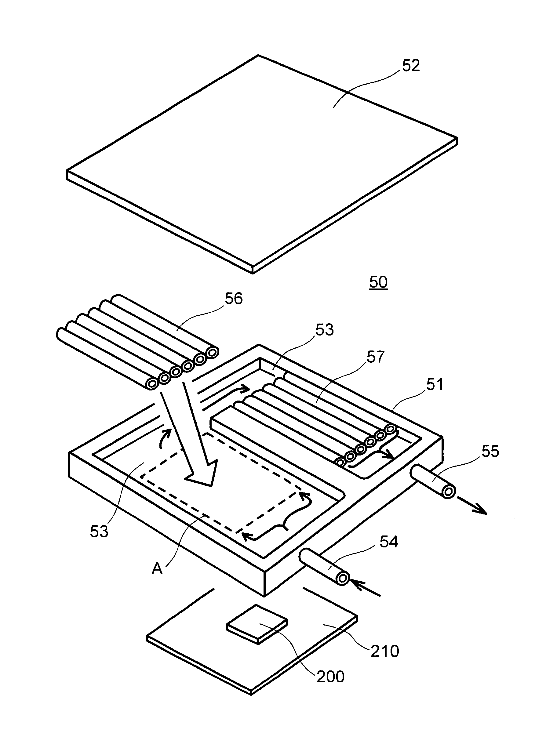
[0023] Hereinafter, embodiments according to the present invention will be fully explained by referring to the attached drawings.

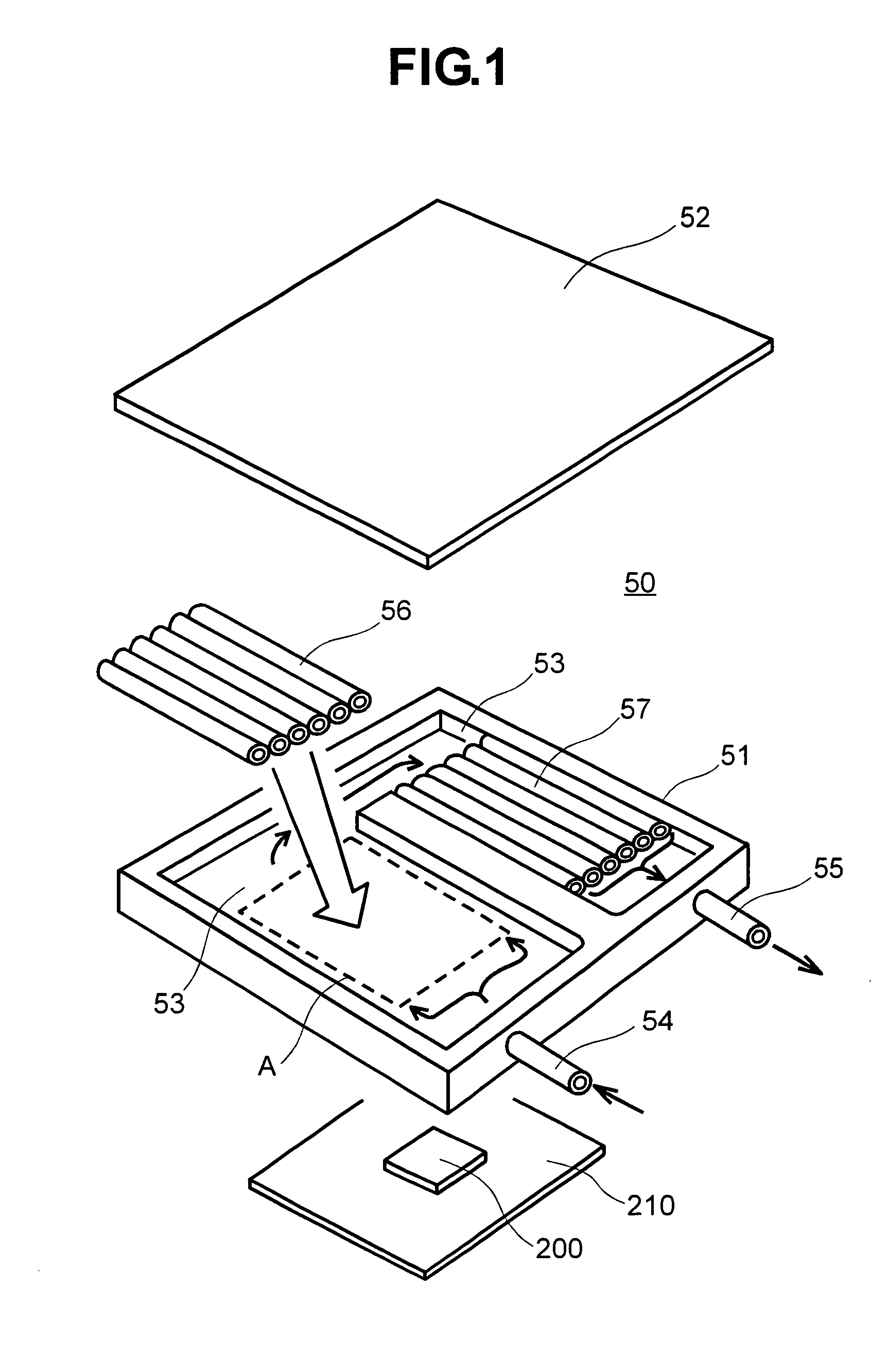
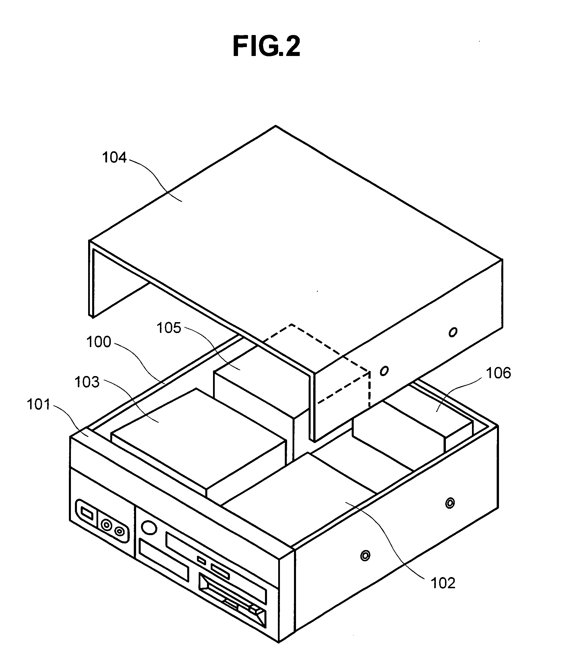
[0024] First of all, FIG. 2 attached herewith shows an example of the entire structure of an electronic apparatus having a liquid-cooling system therein, according to an embodiment of the present invention. However, in the present example, there is shown a case where the present invention is applied into a main body of a desktop-type personal computer, for example.

[0025] The main body of the desktop-type personal computer has, as shown in the figure, a housing 100, which is made from a metal plate forming into a cubic shape, for example, on a front panel portion 101 of which are provided various kinds of switches, including, such as, an electric power switch, for example, and also connector terminals and an indicator lamp, etc. In an inside thereof is disposed a driver apparatuses 102 for driving various kinds of external information recording media, suc...


PUM


Abstract

For providing an electronic apparatus, having a cooling system therein, for enabling cooling operation of a CPU 200, which is mounted within a housing 100 of the apparatus and needs cooling thereof, the cooling system for cooling the CPU has a cooling jacket 50, a radiator 60, and a circulation pump 70, wherein the cooling jacket comprises a base-plate portion 51, being made of a material superior in heat transfer, such as, copper or the like, and formed with a flow inlet 54 and a flow outlet 55 for the liquid coolant, as well as, a flow passage formed in “U” or “I” shape within an inside thereof, and a cover portion 52, and in a portion of the flow passage of the “U” or “I” shape is disposed a coolant division portion 56 or / and 57, being made up by combining a plural number of pieces of fine tubes in a bundle, each of which is also made of a material superior in the heat transfer, such as copper or the like, through brazing.

Description

BACKGROUND OF THE INVENTION [0001] The present invention relates to an electronic apparatus, such as, a personal computer of being so-called a desktop type or a notebook type, and / or a server etc., for example, and in particular, it relates to an electronic apparatus having a liquid cooling system therein, for enabling to cool down a semiconductor integrated circuit (IC) element(s), i.e., a heat-generating element, that is mounted within an inside thereof, effectively, with an aid of a liquid coolant. [0002] In general, cooling is necessary for the semiconductor IC element, which constitutes a heat-generating body within an electronic apparatus, such as, a personal computer of so-called the desktop type or the notebook type, and / or a server etc., in particular, a CPU (Central Processing Unit), so as to ensuring the normal operation thereof. For that purpose, conventionally, it is common to achieve the cooling for it, with using a heat transfer material, with which fins are formed in...

Claims


Application Information

Patent Timeline
IPC IPC(8): F28F1/22F25D9/00F28F13/02F28F13/06G06F1/20H01L23/473H05K7/20
CPCF28D2021/0029F28F1/22F28F3/12F28F13/02F28F13/06H01L2924/0002H01L23/473H01L2924/00H05K7/20
Inventor OHASHI, SHIGEONAGANAWA, TAKASHIMINAMITANI, RINTARONISHIHARA, ATSUO
Owner HITACHI LTD
Features
  • Generate Ideas
  • Intellectual Property
  • Life Sciences
  • Materials
  • Tech Scout
  • Unparalleled Data Quality
  • Higher Quality Content
  • 60% Fewer Hallucinations
Learn More